The Critical Role of Differential Backlash in Axle Rebuilds
When executing comprehensive differential rebuild procedures, setting the correct differential backlash is arguably the most meticulous and consequential step in the entire process. Backlash refers to the microscopic rotational play or clearance between the mating teeth of the ring and pinion gears. If the backlash is too tight, the gears will bind, generate excessive heat, and ultimately seize or strip the teeth off the ring gear. If the backlash is too loose, the axle will exhibit a harsh clunking noise upon load reversal, leading to impact fractures on the gear teeth and catastrophic failure.
As modern drivetrains push higher torque figures through smaller, more efficient axle housings, the margin for error has shrunk. In 2026, with the widespread adoption of high-horsepower EV swaps and heavily modified off-platform trucks, mastering the step-by-step measurement and adjustment of differential backlash is a mandatory skill for any drivetrain specialist. This guide details the exact procedures, shim mathematics, and torque specifications required to blueprint a differential for maximum longevity.
Essential Tools for Precision Measurement
Before beginning the rebuild, ensure your workbench is equipped with the following precision instruments. Guesswork has no place in gear setup.
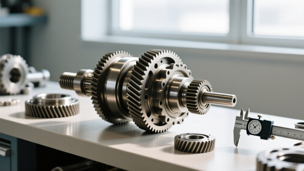
- Dial Indicator with Magnetic Base: A high-quality indicator with a minimum resolution of 0.0001 inches (e.g., Mitutoyo 2416S). Standard automotive feeler gauges are entirely inadequate for this task.
- Beam-Style Inch-Pound Torque Wrench: Required for accurately measuring pinion bearing rotational preload. Click-style torque wrenches are not sensitive enough for the 15-30 in-lb range.
- Carrier Bearing Puller and Installer: To safely remove and press bearings without damaging the races or cages.
- Yellow Gear Marking Compound: Zinc-oxide based paste for verifying the contact pattern.
- Shim Kit: A comprehensive master shim kit (e.g., Motive Gear SK SS-1) covering increments from 0.001" to 0.050".
Step 1: Establish Pinion Depth Before Backlash
A common and fatal rookie mistake is attempting to set differential backlash before establishing the correct pinion depth. Pinion depth dictates how deeply the pinion gear meshes into the ring gear's pitch line. Changing the pinion depth will inherently alter your backlash, but changing your backlash (via carrier shims) will not alter your pinion depth.
Therefore, you must first set the pinion depth using the pinion head marking (e.g., a "+2" or "-1" etched on the pinion head indicating thousandths of an inch deviation from nominal). Use a pinion depth setting tool or measure from the ring gear centerline to the pinion head face using a caliper and specialty fixture. Only once the pinion depth is verified and the pinion bearing preload is set (typically 20-28 in-lbs of rotational drag for new bearings on a Ford 8.8) should you move on to the carrier and backlash adjustment.
Step 2: Mounting the Dial Indicator
Proper placement of the dial indicator is crucial for accurate sweep readings. Attach the magnetic base to a solid, non-moving surface, such as the differential housing or a heavy steel table if the housing is secured in a vise.
Position the indicator's plunger so it rests against the drive side (the convex side) of a ring gear tooth. The plunger must be situated as close to the outer edge (the heel) of the ring gear as possible, and it must be perfectly perpendicular to the tooth face. Any angular deviation will result in a cosine error, yielding falsely low backlash readings. Pre-load the indicator by about 0.050" to ensure it can read both positive and negative movement without bottoming out.
Step 3: Measuring the Initial Differential Backlash
With the carrier installed and the bearing caps lightly snugged (but not fully torqued, to allow for shim adjustments), secure the pinion flange to prevent it from rotating. You can use a specialized flange holding tool or wrap a heavy leather strap around the yoke.
Gently rock the ring gear back and forth by hand. Do not use a pry bar, as this will deflect the housing and skew the data. Observe the dial indicator sweep. Record this measurement. Next, rotate the ring gear 120 degrees and repeat the measurement. Do this a third time at 240 degrees. Ring gears are not perfectly concentric; you must base your shim calculations on the tightest reading of the three to ensure the gears never bind during full rotation.
Step 4: The Shim Mathematics of Backlash Adjustment
Once you have your tightest baseline reading, you must adjust the carrier shims to bring the differential backlash into specification. Most solid-axle differentials (like the GM 10-bolt, Ford 8.8, and Dana 44) use carrier shims located behind the pressed-on bearing races.
The Golden Rule of Shim Adjustment: To decrease backlash (move the ring gear closer to the pinion), you must add shim thickness to the ring gear side and subtract the exact same thickness from the opposite side. This maintains your carrier bearing preload.
Real-World Shim Calculation Example (Ford 8.8 Axle)
- Target Backlash: 0.008" - 0.012" (Let's aim for 0.010")
- Measured Tightest Backlash: 0.018" (Too loose by 0.008")
- Current Left Shim Pack (Ring Gear Side): 0.140"
- Current Right Shim Pack (Opposite Side): 0.135"
The Fix: You need to move the ring gear 0.008" closer to the pinion. You will add 0.008" to the Left Shim Pack (making it 0.148") and subtract 0.008" from the Right Shim Pack (making it 0.127"). Pull the carrier, swap the shims, reinstall, and re-measure. It is common to repeat this process two or three times to dial in the exact thousandth.
Step 5: Verifying the Gear Contact Pattern
Backlash numbers alone do not guarantee a quiet, long-lasting gear set. You must verify the physical contact pattern. Apply a thin, even coat of yellow gear marking compound to the coast and drive sides of three or four ring gear teeth.
Using a wrench on the pinion nut, apply moderate rotational resistance to the ring gear while turning the pinion through the marked teeth. Inspect the pattern:
- Ideal Pattern: Centered between the top (face) and bottom (flank) of the tooth, and centered between the heel (inner edge) and toe (outer edge).
- High Flank / Low Face: Indicates the pinion is too deep or too shallow. If the pattern is high on the flank, the pinion needs to be moved away from the ring gear (requires changing the pinion depth shim, which means starting over with backlash).
- Heel / Toe Bias: If the pattern is heavily biased toward the heel or toe, it usually indicates improper backlash or a mismatched gear set.
For deeper insights into reading complex gear patterns, consult the technical documentation provided by Yukon Gear & Axle Technical Support, which offers excellent visual guides for diagnosing pattern anomalies.
Step 6: Final Torque and Staking
Once the differential backlash is perfectly set and the contact pattern is verified, it is time to lock everything down. Torque the carrier bearing cap bolts to the manufacturer's exact specification. For a Dana 44, this is typically 65 ft-lbs; for a Ford 8.8, it is 85 ft-lbs. Always use a calibrated torque wrench and apply a drop of medium-strength threadlocker (blue Loctite) to the cap bolt threads to prevent backing out under high-vibration off-road use.
If your axle utilizes threaded carrier adjusters (common in Toyota Land Cruiser axles and Dana 60s), ensure you lock the adjuster nuts with the factory tabbed lock rings and stake them securely with a brass drift to prevent them from walking out during operation.
Target Specifications for Common Axle Platforms
Reference the table below for baseline specifications. Always verify with the specific gear manufacturer's insert, as aftermarket ratios (e.g., 4.88 or 5.13) sometimes require slight deviations from OEM specs.
| Axle Model | Target Backlash | Pinion Preload (New Bearings) | Carrier Cap Torque |
|---|---|---|---|
| Ford 8.8" (IRS & Solid) | 0.008" - 0.012" | 20 - 28 in-lbs | 85 ft-lbs |
| Dana 44 (Standard) | 0.006" - 0.010" | 20 - 30 in-lbs | 65 ft-lbs |
| GM 8.5" / 8.6" 10-Bolt | 0.006" - 0.010" | 15 - 25 in-lbs | 70 ft-lbs |
| Dana 60 (Front/Rear) | 0.006" - 0.010" | 25 - 35 in-lbs | 120 ft-lbs |
| Toyota 8" (V6/Tacoma) | 0.005" - 0.007" | 18 - 25 in-lbs | 58 ft-lbs (Adjuster Lock) |
Post-Rebuild Differential Fluid Selection and Break-In
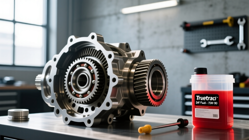
Because the mechanical longevity of your rebuild is entirely dependent on proper lubrication during the critical mating phase, differential fluid selection is the final, vital step of the rebuild procedure. Aftermarket ring and pinion sets (such as those from Motive Gear or Yukon) are typically not factory-lapped. This means the initial 500 miles of driving will generate significant friction and heat as the gears wear into their final mating pattern.
The Break-In Fill: Do not use full synthetic gear oil for the initial break-in. Synthetic oils possess advanced friction modifiers and extreme pressure (EP) additives that are too slippery, preventing the gears from properly lapping together. Instead, fill the housing with a high-quality, conventional petroleum-based 80W-90 GL-5 gear oil. The sulfur-phosphorus ZDDP chemistry in conventional GL-5 oils provides the necessary boundary lubrication to protect the gear faces without inhibiting the micro-wearing required for lapping.
The 500-Mile Service: After exactly 500 miles of mixed driving (avoiding sustained highway speeds over 65 mph and heavy towing during this period), drain the break-in fluid. You will likely notice a metallic sheen on the fluid and a distinct sulfur smell—this is normal and indicates the gears are wearing in. Flush the housing with a cheap quart of conventional oil to remove suspended metallic particulates.
The Long-Term Fill: Refill the differential with a premium full synthetic 75W-90 GL-5 fluid, such as Amsoil Severe Gear or Red Line ShockProof. Synthetic fluids offer vastly superior thermal stability, resisting the viscosity breakdown that causes gear whine in heavily loaded differentials. If your rebuild included a clutch-type limited-slip differential (LSD), ensure you add the exact OEM-specified friction modifier (e.g., Motorcraft XL-3 or GM EOS) to prevent chatter during low-speed cornering, while being careful not to over-add, which can cause the clutches to slip excessively under hard acceleration.
For comprehensive fluid compatibility charts and further rebuild troubleshooting, Randy's Ring & Pinion maintains an excellent database of axle-specific fluid capacities and modifier requirements. By marrying precise mechanical backlash setup with strict fluid break-in protocols, your differential rebuild will deliver thousands of miles of silent, bulletproof operation.