The 'DGPS' Metaphor: Why Gear Setup Demands Extreme Precision
When beginners first research axle rebuilding, they might stumble across the term differential global positioning system—a satellite navigation concept that occasionally crosses wires in search algorithms with automotive differentials. While DGPS uses ground-based reference stations to correct GPS signal errors down to the centimeter, setting up a ring and pinion gear requires a mechanical 'positioning system' accurate to the thousandth of an inch. In the world of drivetrain mechanics, there is no room for signal drift; a variance of just 0.003 inches in pinion depth or backlash will result in catastrophic gear whine, accelerated wear, or total differential failure.
This beginner-friendly explainer will demystify the ring and pinion setup process. Whether you are rebuilding a classic Dana 44, a Ford 8.8 IRS, or a heavy-duty GM 14-bolt, the physics of gear meshing remain identical. We will break down the tools, the measurements, and the fluid dynamics required to achieve perfect gear alignment.
Anatomy of a Differential Setup
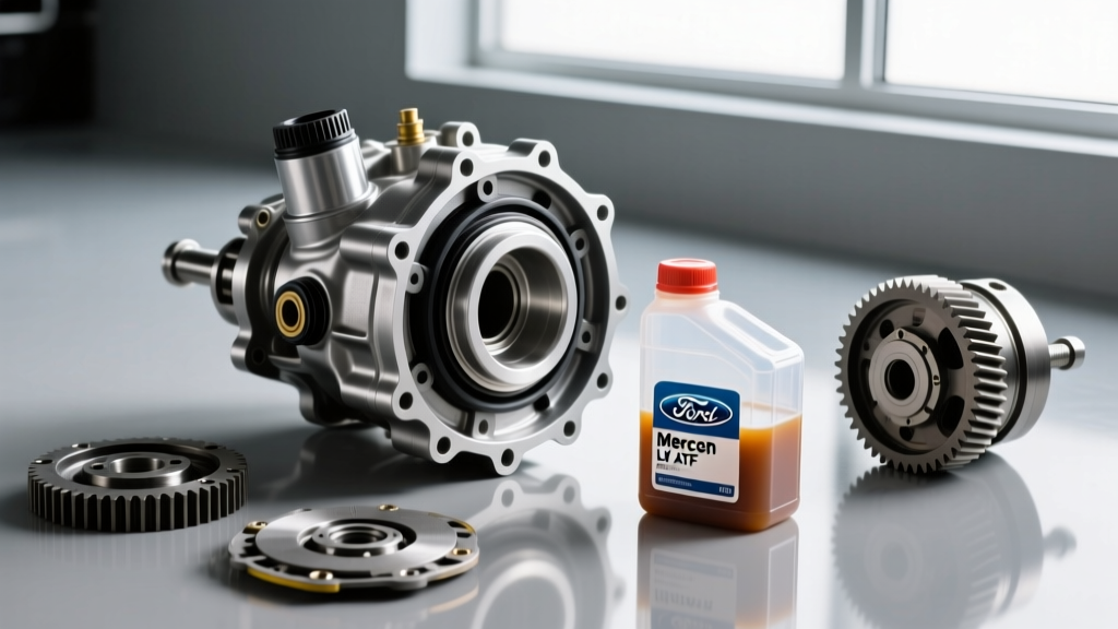
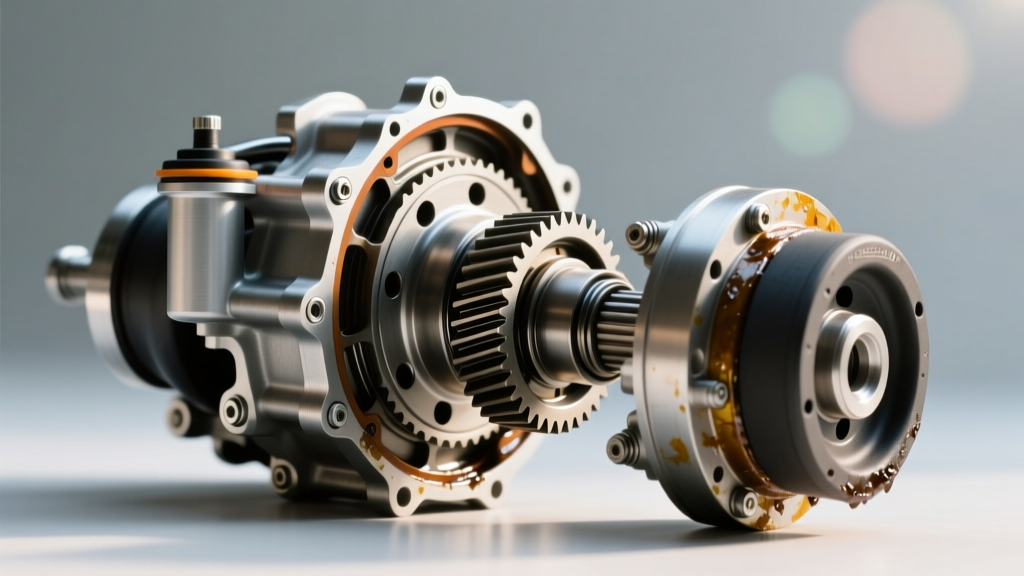
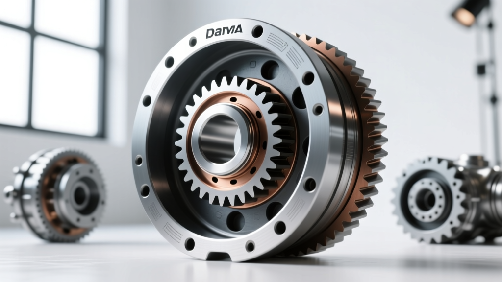
Before turning a single wrench, you must understand the spatial relationship between the pinion gear (attached to the driveshaft) and the ring gear (bolted to the carrier). These gears operate on a hypoid design, meaning the pinion centerline is offset below the ring gear centerline. This offset allows for larger pinion teeth and smoother engagement, but it introduces extreme sliding friction that necessitates precise shimming and specialized extreme pressure (EP) gear oils.
Essential Tools and Part Numbers
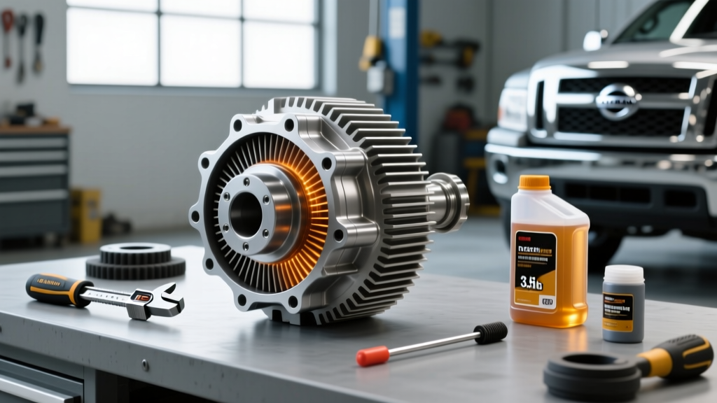
Do not attempt a gear setup with standard hand tools alone. You need precision measuring instruments. According to Yukon Gear & Axle, a proper setup requires the following:
- Dial Indicator with Magnetic Base: Must read in 0.001-inch increments to measure backlash accurately.
- Inch-Pound Torque Wrench: Crucial for measuring pinion bearing preload (do not confuse this with a standard foot-pound torque wrench).
- Bearing Puller & Press: For removing and installing pinion and carrier bearings without damaging the cages.
- Setup Bearings: These are bearings with slightly enlarged inner diameters (or honed-out old bearings) that allow you to slide the pinion and carrier in and out by hand during the trial-and-error shimming phase.
- Master Setup Kit: For example, the Yukon SK SETUP-D44 kit includes all necessary pinion depth shims, carrier shims, crush sleeves, and pinion nuts for a Dana 44 axle.
The Four Pillars of Gear Positioning
Achieving that 'differential global positioning system' level of accuracy requires balancing four distinct measurements. Adjusting one will almost always affect the others, which is why patience is your most valuable tool.
1. Pinion Depth
Pinion depth dictates how far the pinion gear sits into the ring gear. It is adjusted via shims placed between the pinion bearing and the pinion head (inner shim) or under the pinion bearing race (outer shim, depending on the axle design). The target depth is usually stamped on the face of the pinion gear (e.g., '+0.002' means the pinion needs to sit 0.002 inches deeper than the nominal factory baseline).
2. Pinion Bearing Preload
Preload is the rotational resistance of the pinion bearings when the seal and axle shafts are removed. It eliminates bearing play and ensures the pinion doesn't deflect under heavy torque loads.
Target Specs:
- New Bearings: 25 to 35 inch-pounds of rotational torque.
- Used/Broken-in Bearings: 15 to 20 inch-pounds.
Expert Warning: On axles using a crush sleeve (like the Ford 8.8 and Dana 44), achieving preload requires tightening the pinion nut to massive torque values—typically 225 ft-lbs for the Ford 8.8 and 240 ft-lbs for the Dana 44. Always use a new crush sleeve and a new staked pinion nut for final assembly. If you over-crush the sleeve, you must replace it and start over.
3. Backlash
Backlash is the amount of rotational 'slop' or clearance between the ring and pinion teeth. It is adjusted by moving the entire carrier assembly left or right using threaded adjusters (Chrysler/Dana style) or by swapping carrier shims (Ford/GM style).
Target Spec: Generally 0.006 to 0.010 inches for street-driven passenger vehicles. Heavy-duty off-road applications may run up to 0.012 inches to account for thermal expansion and housing deflection under load.
4. Carrier Bearing Preload
Just like the pinion, the carrier bearings require preload to prevent the ring gear from wobbling under load. This is achieved by adding a specific amount of shim thickness (usually 0.004 to 0.008 inches over the zero-clearance measurement) to the carrier assembly before pressing it into the housing.
Decoding the Gear Contact Pattern
Numbers on a dial indicator only tell half the story. The ultimate proof of your mechanical 'positioning' is the gear contact pattern. By painting three to four teeth on the ring gear with yellow gear marking compound and rotating the gears under moderate resistance (using a rag wrapped around the pinion yoke), you can read how the gears are mating.
| Pattern Indicator | Visual Cue on Ring Gear Tooth | Corrective Action Required |
|---|---|---|
| Ideal Pattern | Centered on the tooth face, slightly biased toward the heel under load, covering 50-75% of the tooth width. | None. Proceed to final assembly and fluid fill. |
| Pinion Too Deep | Pattern is concentrated on the root (bottom) of the ring gear tooth. | Decrease pinion depth shim thickness to move pinion away from ring gear. |
| Pinion Too Shallow | Pattern is concentrated on the flank/top land (top edge) of the ring gear tooth. | Increase pinion depth shim thickness to move pinion closer to ring gear. |
| Backlash Too Tight | Pattern is pushed heavily toward the toe (inner edge) of the tooth. | Increase backlash by moving carrier away from the pinion. |
| Backlash Too Loose | Pattern is pushed heavily toward the heel (outer edge) of the tooth. | Decrease backlash by moving carrier closer to the pinion. |
For deeper technical visual guides, Randy's Ring & Pinion offers extensive pattern-reading charts that account for the differences between drive (acceleration) and coast (deceleration) patterns. Always prioritize the drive pattern for street vehicles, as this is where the majority of torque is applied.
The Break-In Procedure and Fluid Chemistry
Because this guide falls under the differential fluid and maintenance umbrella, it is critical to understand that a perfect gear setup will still fail if the break-in procedure and fluid chemistry are ignored. Hypoid gears generate immense localized heat during the first 500 miles of operation as the microscopic machining peaks on the gear teeth wear into one another.
Selecting the Right Fluid
You must use an API GL-5 rated gear oil. GL-5 fluids contain high levels of sulfur-phosphorus extreme pressure (EP) additives that create a sacrificial chemical film on the gear teeth, preventing metal-to-metal welding under high sliding loads.
For most Dana and Ford axles, a 75W-90 Full Synthetic (like Amsoil Severe Gear or Royal Purple Max Gear) is ideal. If you are running a heavy-duty 1-ton truck or towing consistently, step up to an 85W-140 to maintain film strength at elevated differential temperatures.
Note on Limited Slips: If your carrier is a clutch-type limited-slip differential (LSD) like a Ford Trac-Lok or Dana Powr-Lok, you must add a friction modifier (e.g., 4 oz of OEM Ford XL-3 or equivalent) to prevent clutch chatter during low-speed cornering. Torque-sensing differentials (like the Torsen or Detroit Truetrac) do not require friction modifiers.
The 500-Mile Break-In Protocol
According to Dana Spicer engineering guidelines, the break-in cycle is non-negotiable:
- First 15 Miles: Drive under light load. The differential housing will become hot to the touch. Stop and let the axle cool completely to ambient temperature. This initial heat cycle allows the gear oil to penetrate the micro-pores of the metal.
- Next 100 Miles: Drive normally, but avoid wide-open throttle, heavy towing, or sustained highway speeds over 65 MPH. Vary your speed frequently to ensure different sections of the ring gear teeth mate with the pinion.
- 100 to 500 Miles: Normal driving is permitted, but keep towing loads under 50% of the vehicle's maximum capacity.
- 500-Mile Mark: Drain the break-in fluid. You will likely see a fine, glittery metallic paste on the drain plug magnet. This is normal; it is the remnants of the manufacturing peaks wearing off. Refill with fresh GL-5 gear oil and your LSD additive. Your differential is now fully seated and ready for maximum torque loads.
Final Thoughts on Drivetrain Precision
Setting up a ring and pinion is not black magic; it is an exercise in methodical measurement and patience. By treating your dial indicator and inch-pound torque wrench with the same reverence a surveyor gives to a differential global positioning system, you will achieve a whisper-quiet, bulletproof axle assembly capable of handling hundreds of thousands of miles or thousands of horsepower. Take your time, read the pattern, and respect the fluid dynamics, and your drivetrain will reward you with flawless performance.