Understanding the Transmission Range Sensor Circuit Malfunction
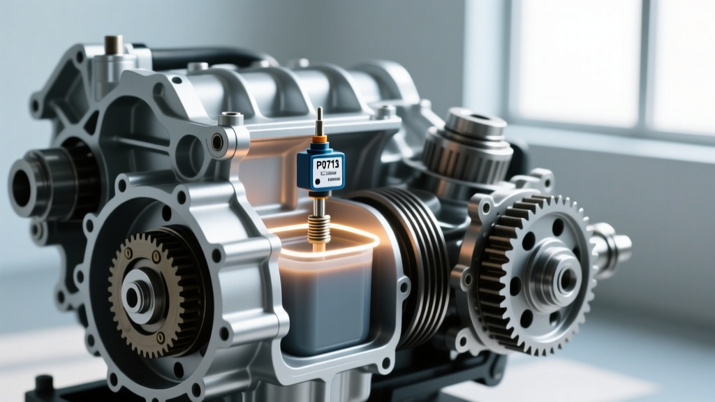
In modern powertrain management, the Transmission Control Module (TCM) relies on absolute certainty regarding the driver's gear selection. When the TCM receives illogical, erratic, or absent voltage signals from the gear position switch, it logs a transmission range sensor circuit malfunction. This typically manifests as Diagnostic Trouble Codes (DTCs) in the P0705 to P0709 range. For automotive technicians and advanced DIYers, resolving these codes requires moving beyond simple parts-swapping and adopting a rigorous transmission electrical troubleshooting methodology.
A range sensor malfunction is not merely an inconvenience; it is a critical safety and drivability fault. When the TCM cannot verify whether the vehicle is in Park, Reverse, Neutral, or Drive, it will often trigger a fail-safe or 'limp-home' mode, defaulting to a single forward gear and disabling the starter relay to prevent the vehicle from cranking in gear. In this comprehensive preventive maintenance and diagnostic guide, we will explore the electrical architecture of these sensors, outline precise multimeter testing procedures, and establish maintenance protocols to prevent future circuit degradation.
The Binary Logic of Range Sensing
To effectively troubleshoot the circuit, you must first understand how the TCM interprets gear position. Most traditional external Transmission Range (TR) sensors utilize a series of four or five internal switches (often labeled A, B, C, and P) that open and close to ground or a 5-volt reference. By reading the binary combination of these circuits, the TCM determines the exact shifter position.
Expert Insight: If your scan tool displays 'Drive' while the shifter is physically in 'Reverse', you are likely looking at a short to ground on one of the signal circuits, or severe internal corrosion causing cross-talk between adjacent pins on the sensor harness connector.
According to standard OBD-II diagnostic protocols for P0705, a circuit malfunction is flagged when the TCM sees a combination of switch states that is mechanically impossible. For example, if the 'Park' circuit and the 'Drive' circuit are simultaneously closed, the TCM recognizes the electrical fault and sets the code.
Generational Architecture Shifts: External vs. Internal
Electrical troubleshooting varies wildly depending on the transmission family you are servicing. The physical location of the sensor dictates the diagnostic approach:
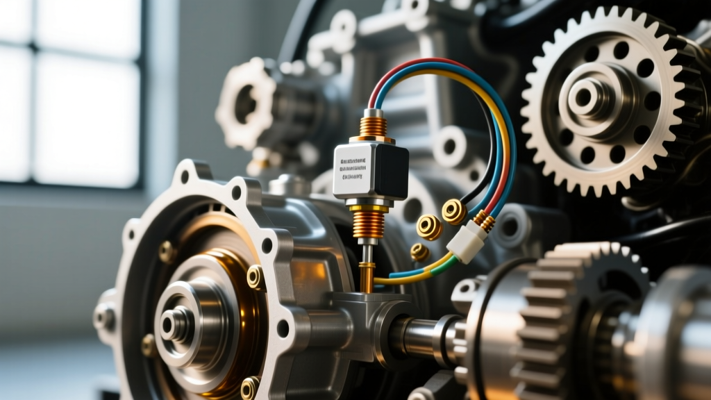
- External TR Sensors (e.g., Ford 6R80, GM 4L60E): Mounted on the exterior of the transmission case, linked to the shift shaft. These are exposed to road debris, water intrusion, and engine bay heat cycles. Troubleshooting focuses on connector corrosion, harness chafing, and mechanical misalignment.
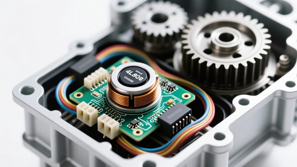
- Internal Mode Switches (e.g., GM 6L80 / 6L90): The TR sensor is integrated into the Transmission Electro-Hydraulic Control Module (TEHCM) or mounted internally on the valve body. Failures here are often caused by conductive clutch material contaminating the transmission fluid, which bridges the microscopic gaps on the sensor's printed circuit board.
- Integrated Mechatronic Units (e.g., ZF 8HP, GM 10L90): Modern 8-speed and 10-speed transmissions utilize Hall-effect sensors embedded deep within the mechatronic valve body assembly. There is no external linkage. Electrical troubleshooting requires verifying the integrity of the high-speed CAN bus and the main case-to-harness bulkhead connector, as internal repairs usually mandate a complete mechatronic unit replacement and proprietary OEM programming.
Step-by-Step Electrical Troubleshooting Protocol
When faced with a persistent transmission range sensor circuit malfunction, avoid the temptation to immediately replace the sensor. Follow this systematic electrical diagnosis using a high-impedance digital multimeter (DMM) like the Fluke 87V.
Step 1: Verify the 5-Volt Reference and Ground
Disconnect the TR sensor harness connector. Turn the ignition to the 'ON' position (engine off). Using your DMM, back-probe the harness side of the connector. You should read a stable 4.8V to 5.2V on the reference wire (consult your specific OEM wiring diagram for the exact pinout). Next, check the ground circuit. A voltage drop test across the ground wire to the battery negative terminal should read less than 0.05V. If the 5V reference is missing, the fault lies in the TCM or a shared splice pack, not the sensor itself.
Step 2: Signal Circuit Continuity and Short Testing
With the harness still disconnected and the ignition off, test the signal wires from the TR sensor connector back to the TCM connector for continuity. You are looking for less than 1.0 ohm of resistance. Next, check each signal wire for a short to ground and a short to power. A common failure point on vehicles like the Chevy Silverado is harness chafing where the wiring loom rubs against the bellhousing or exhaust heat shield, causing intermittent shorts that only appear when the vehicle is vibrating under load.
Step 3: Component Testing (Sensor Sweep)
Reconnect the harness and use T-pins to carefully back-probe the signal wires at the connector. Connect your DMM to the signal circuits. Have an assistant slowly move the gear shifter from Park through Low. You should see the voltage states toggle cleanly between 0V (closed/grounded) and 5V (open). If the voltage fluctuates erratically or 'floats' between 1.5V and 3.5V during the sweep, the internal contacts of the TR sensor are heavily oxidized or worn, confirming the need for replacement.
Preventive Maintenance: Stopping Malfunctions Before They Start
As a core tenet of transmission electrical troubleshooting, preventing circuit degradation is far more cost-effective than replacing TEHCMs or mechatronic units. Implement the following preventive maintenance steps during routine service intervals:
- Bulkhead Connector Care: On ZF and GM 10-speed units, the main electrical pass-through connector (bulkhead) is a prime entry point for moisture. During every fluid service, disconnect this plug, inspect for green copper oxide corrosion, and clean it with specialized electrical contact cleaner. Apply a thin layer of dielectric grease to the weather seal, not directly on the pins, to prevent hydro-locking the connector.
- Harness Loom Inspections: Inspect the final 12 inches of the transmission harness. Re-wrap any sections where the split-loom tubing has degraded, and secure the harness with high-temperature P-clips to maintain a minimum 2-inch clearance from exhaust components.
- Fluid Conductivity Management: For transmissions with internal range sensors (like the GM 6L80), adherence to strict fluid change intervals (every 45,000 to 60,000 miles under severe duty) is vital. As clutch friction material wears, it becomes suspended in the fluid, turning the ATF into a mild conductor. This causes micro-shorts across the internal mode switch traces. Dropping the pan and replacing the filter removes this conductive sludge.
- Chemical Contact Enhancement: If you detect minor voltage drops across an aging external TR sensor connector, apply a drop of Stabilant 22 or equivalent contact enhancer to the pins. This resin-based compound fills microscopic air gaps, preventing oxidation without causing cross-pin shorting.
Reference Matrix: TRS Specifications, Torque, and Costs
The following table provides critical reference data for some of the most common transmission platforms encountered in modern repair facilities. Always verify exact specifications against the OEM service manual for your specific model year.
| Transmission Model | Sensor Type / Location | Common OEM Part Number | Fastener Torque Spec | Est. Part Cost (2026) |
|---|---|---|---|---|
| GM 6L80 / 6L90 | Internal Mode Switch (IMS) | ACDelco 24253109 (TEHCM Kit) | 11 Nm (97 lb-in) | $650 - $950 |
| Ford 6R80 | External TR Sensor | Motorcraft SW-7188 (BL3Z-7F247-A) | 8 Nm (71 lb-in) | $55 - $85 |
| GM 4L60E / 4L65E | External Park/Neutral Switch | ACDelco D1906C | 12 Nm (106 lb-in) | $40 - $65 |
| ZF 8HP (845/890) | Integrated Mechatronic Hall Sensor | N/A (Sold as full Mechatronic) | Case Bolts: 10 Nm | $1,200 - $1,800+ |
Note: When replacing the GM 6L80 TEHCM or any ZF Mechatronic unit, the vehicle will require proprietary TCM reprogramming and security theft-deterrent relearn procedures via a J2534 pass-through device or OEM scan tool.
Final Diagnostic Thoughts
A transmission range sensor circuit malfunction is a symptom of a broader electrical or environmental failure. By mastering the binary logic of the sensor circuits, utilizing a high-quality DMM to isolate voltage drops, and implementing rigorous connector and fluid maintenance, you can accurately diagnose the root cause on the first attempt. Whether you are aligning an external Ford 6R80 sensor with a specialized alignment tool or diagnosing conductive fluid sludge in a GM 6L80, methodical electrical troubleshooting remains the hallmark of elite powertrain repair.