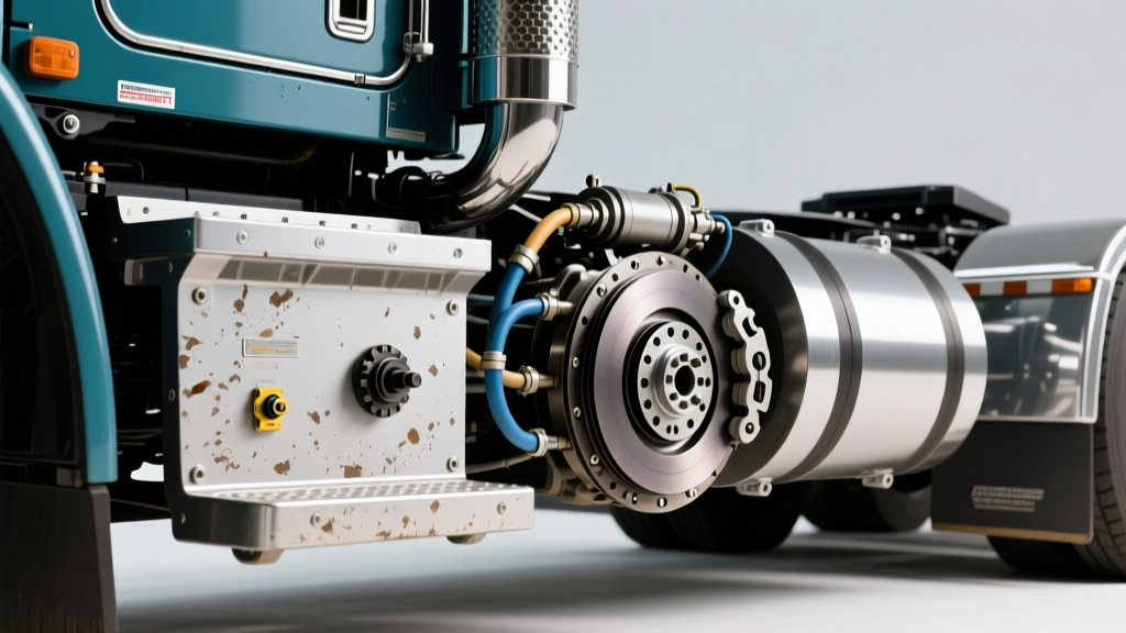
When a heavy-duty Class 8 truck experiences clutch slipping, the immediate assumption by many fleet technicians is a worn friction disc or a failed pressure plate. However, in models like the iconic Peterbilt 379 equipped with Eaton Fuller manual transmissions (such as the RTLO-18918B 18-speed), mechanical failure is frequently preceded by adjustment-induced slipping. A critical, yet often overlooked, component in this diagnostic chain is the clutch pedal bracket assembly. Understanding the exact Peterbilt 379 clutch switch location and its precise adjustment is vital for preventing catastrophic drivetrain failures, eliminating 'ghost slipping,' and avoiding unnecessary $5,000+ clutch replacements.
The Anatomy of Heavy-Duty Clutch Slipping
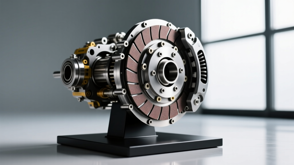
Clutch slipping in a heavy-duty application occurs when the friction disc fails to maintain a locked rotational coupling between the engine flywheel and the transmission input shaft under load. In a 15.5-inch Eaton Fuller SoloAdvantage clutch (Part No. 108946-02), the clamping force exceeds 4,500 lbs. When slipping occurs, it generates immense thermal energy, quickly glazing the organic or ceramic facings and warping the cast-iron pressure plate.
While oil contamination from a failed rear main seal or worn facings are common mechanical culprits, adjustment-induced slipping is the most preventable. If the clutch release bearing is held in constant, even slight, contact with the clutch brake and pressure plate fingers, the clamping force is reduced. This is where the pedal return mechanism and the dash-mounted switches come into play.
Why the Peterbilt 379 Clutch Switch Location Dictates Pedal Return
The Peterbilt 379 utilizes a robust mechanical clutch linkage system (or a heavy-duty hydraulic master/slave setup in later model years) paired with a pedal assist spring. To ensure the pedal returns fully to the upper stop—and to integrate with the truck's electronics—several electrical switches are mounted directly on the pedal arm bracket under the dash.
If these switches are misadjusted, they can physically restrict the pedal's upward travel. Even a 1/8-inch restriction at the pedal pad translates to a critical loss of free play at the release yoke, causing the release bearing to 'ride' the clutch fingers. Over hundreds of miles, this friction generates enough heat to cause the clutch to slip under heavy throttle application in high gears.
Locating and Adjusting the Dash Switches
Finding the Peterbilt 379 clutch switch location requires accessing the under-dash panel above the clutch pedal. You will typically find two primary switches mounted on a slotted bracket:
- Clutch Start Interlock Switch: Prevents the engine from cranking unless the clutch is fully depressed. Located at the bottom of the pedal travel arc.
- Cruise Control Dump / Disengage Switch: Cuts power to the cruise control servos the moment the driver touches the clutch pedal. Located near the top of the pedal travel arc.
The Diagnostic Trap: If the cruise control dump switch is threaded too far into its bracket, the pedal arm will rest against the switch plunger instead of the mechanical rubber upper stop. This holds the clutch linkage slightly engaged. To correct this, loosen the switch locknut (typically requiring a 14mm or 9/16-inch wrench), back the switch out until the pedal rests firmly on the factory rubber bumper, and retighten the locknut to 15-20 lb-in.
Diagnostic Protocol: Is It Slipping or Ghost-Disengaging?
Before tearing down the bellhousing, technicians must perform a systematic diagnosis to differentiate between internal mechanical failure and external linkage/switch interference. Below is a structured diagnostic matrix for Class 8 manual transmissions.
| Symptom Profile | Probable Root Cause | Diagnostic Action |
|---|---|---|
| Slipping under heavy load (high gear, low RPM) | Worn friction facings, oil contamination, or loss of pedal free play | Measure pedal free play; inspect for rear main seal leaks |
| Slipping immediately after clutch replacement | Improper clutch brake squeeze or misadjusted pedal switches | Verify Peterbilt 379 clutch switch location and upper stop contact |
| Clutch chatter or vibration upon engagement | Broken damper springs, warped flywheel, or engine mount failure | Check flywheel runout (Max 0.005 in) and inspect isolator springs |
| Difficulty shifting into gear (grinding) | Failed clutch brake or insufficient pedal travel | Measure clutch brake squeeze (should be 0.5 to 1.0 inch from floor) |
The Heavy-Duty 'Stall Test' Equivalent
Unlike automatic transmissions, you cannot perform a traditional stall test on a manual Eaton Fuller. Instead, perform a High-Gear Lugging Test. Drive the truck on a flat, safe surface and shift into 8th gear (direct or overdrive depending on the RTLO model) at approximately 45 MPH. Apply full throttle. If the engine RPM climbs rapidly without a proportional increase in vehicle speed, the clutch is slipping mechanically. If the RPM struggles to climb and the engine bogs down, the clutch is holding, indicating your slipping complaints may be isolated to specific load conditions or driver perception.
Preventive Maintenance Specs & Torque Values
Preventing clutch slipping requires strict adherence to Eaton Fuller's preventive maintenance intervals. The clutch is a wearable component, but its lifespan (often 400,000 to 750,000 miles) is entirely dependent on linkage geometry. According to Eaton Vehicle Clutches engineering guidelines, maintaining the correct air gap and free play is non-negotiable.
'A clutch that is not allowed to fully engage will slip, generating temperatures in excess of 1,000°F at the friction interface. This thermal shock will permanently alter the metallurgy of the pressure plate and destroy the release bearing.' — Eaton Roadranger Service Guidelines.
Critical Measurement Specifications
When performing a PM inspection on a Peterbilt 379, record the following measurements. If they fall outside these parameters, adjust the mechanical linkage at the clutch fork or the hydraulic master cylinder pushrod:
- Pedal Free Play: 1.5 to 2.0 inches (measured at the center of the clutch pedal pad before resistance is felt).
- Clutch Brake Squeeze: 0.5 to 1.0 inches from the floorboard to the bottom of the pedal pad.
- Release Bearing Travel: Minimum 0.125 inches of clearance between the release bearing face and the clutch brake when the pedal is fully released.
- Switch Locknut Torque: 15-20 lb-in (Ensure the cruise switch does not bear the weight of the pedal return spring).
The Cost of Neglect vs. Proactive Adjustment
The financial implications of ignoring pedal geometry and switch adjustment are severe. Replacing a heavy-duty clutch in a Peterbilt 379 requires dropping the entire rear axle assembly, removing the driveshafts, and unbolting the bellhousing from the engine block (Cummins ISX15 bellhousing-to-block bolts require 35-45 lb-ft of torque upon reassembly). The total cost for a shop to replace an Eaton SoloAdvantage clutch, including the clutch brake (Part No. K-3459-01), release bearing, and labor, routinely ranges from $3,500 to $6,000.
Conversely, verifying the Peterbilt 379 clutch switch location, adjusting the under-dash bracket, and setting the clutch brake squeeze takes less than 20 minutes and costs virtually nothing in parts. For fleet managers and owner-operators, integrating pedal free-play and switch verification into every 50,000-mile PM service is the most cost-effective drivetrain insurance available. For more detailed chassis and drivetrain schematics, technicians can refer to Peterbilt Maintenance Support resources to ensure their specific model year's pedal bracket configuration is correctly mapped.