Decoding the Performance Torque Converter Diagram
Building a high-performance powertrain requires more than just bolting on a larger turbocharger or grinding a more aggressive camshaft. The true bottleneck in many modified vehicles lies in the fluid coupling between the engine and the transmission. Understanding the internal architecture through a detailed torque converter diagram is the first step toward unlocking your drivetrain's potential. While a standard OEM converter is designed for fuel economy and low-RPM drivability, a performance unit is engineered to manipulate fluid dynamics, multiplying torque precisely where your engine makes its peak power.
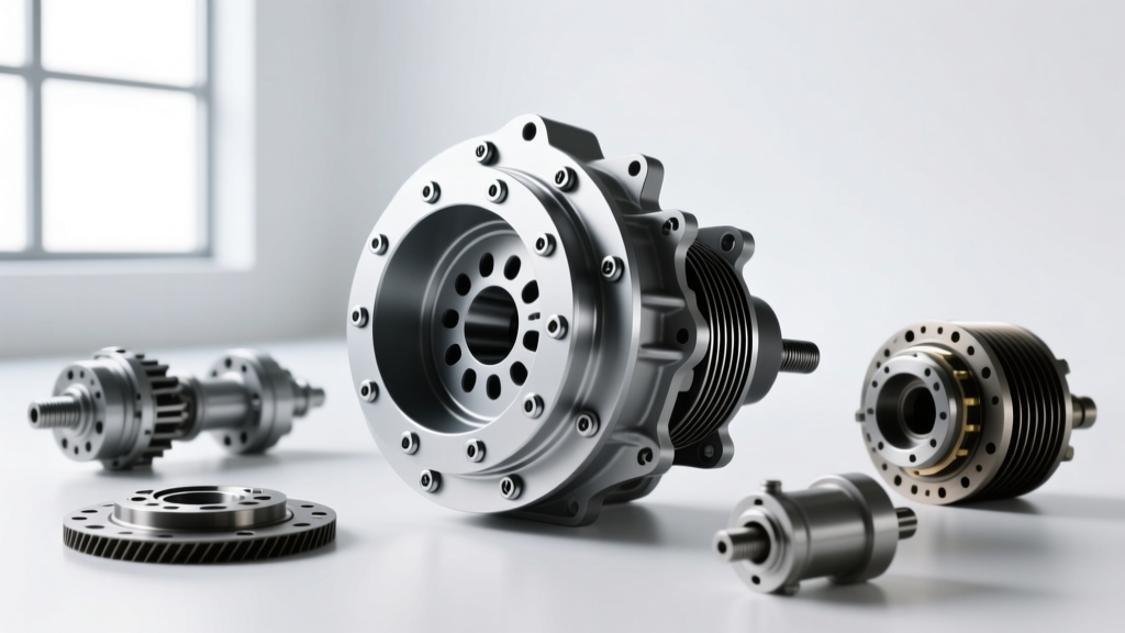
When reviewing a performance torque converter diagram, you will notice several critical upgrades over stock cast units. The most prominent is the billet steel front cover. In factory converters, the stamped steel cover is prone to 'ballooning'—expanding outward under high hydraulic pressure and centrifugal force. At 6,000 RPM and 600+ horsepower, a stock cover can expand up to 0.040 inches, destroying internal clearances and causing catastrophic transmission failure. Performance diagrams illustrate the use of CNC-machined billet covers and anti-ballooning plates to maintain structural rigidity under extreme stress.
Internal Fluid Dynamics: Impeller, Turbine, and Stator
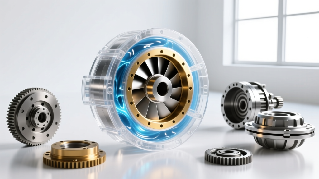
The heart of the converter relies on three main components. The impeller (pump) is driven directly by the engine and throws transmission fluid outward. The turbine catches this fluid, transferring energy to the transmission input shaft. However, the magic happens in the stator, located between the two. In a performance application, the stator's fin angles are radically altered. As of 2026, aftermarket manufacturers are utilizing computational fluid dynamics (CFD) to design stator fins that aggressively redirect fluid back into the impeller, maximizing torque multiplication (often achieving a 2.4:1 to 2.8:1 ratio) while minimizing parasitic slip at higher RPMs.
Stall Speed Selection for Modified Engines
The most common mistake enthusiasts make when upgrading their drivetrain is selecting the wrong stall speed. 'Flash stall' is the true RPM at which the converter transitions from fluid coupling to the torque multiplication phase under wide-open throttle (WOT). Matching this to your engine's torque curve is critical.
Expert Rule of Thumb: Your converter's flash stall speed should be at least 500 to 800 RPM below your engine's peak torque RPM, but high enough to allow the engine to idle in gear without excessive brake creep.
Below is a data matrix to help you match your camshaft profile to the correct converter specifications.
| Camshaft Advertised Duration | Engine Peak Torque RPM | Recommended Flash Stall Range | Typical Application |
|---|---|---|---|
| 260° - 270° | 3,500 - 4,000 | 2,200 - 2,800 RPM | Mild Street / Towing |
| 275° - 285° | 4,200 - 4,800 | 3,000 - 3,600 RPM | Street/Strip / Pro-Touring |
| 290° - 305° | 5,000 - 5,800 | 4,000 - 4,800 RPM | Dedicated Drag / Race |
| 310°+ (Solid Roller) | 6,000+ | 5,500 - 7,000+ RPM | Outlaw / No-Prep Drag |
Real-World Upgrades: 4L60E and 6L80 Case Studies
Let's examine two of the most popular GM transmissions in the performance space and how to properly spec and install a performance converter for each.
The 4L60E / TH350 Platform
For a 450-horsepower street/strip 4L60E build, a 3,200-3,500 RPM stall converter is the sweet spot. Brands like TCI Auto and Circle D Specialties offer excellent billet options in the $650 to $850 range. When installing, the physical setup is just as critical as the internal components. You must maintain a precise 0.125-inch to 0.187-inch gap between the flexplate and the converter's mounting pads. If the converter is forced forward by the transmission bolts to meet the flexplate, you will destroy the front pump gear and the transmission will fail within 50 miles. Always use Grade 10.9 or ARP fasteners (such as ARP 230-7303), torquing the flexplate-to-converter bolts to 46 lb-ft with a medium-strength threadlocker like Loctite 242.
The 6L80 / 8L90 Modern Platform
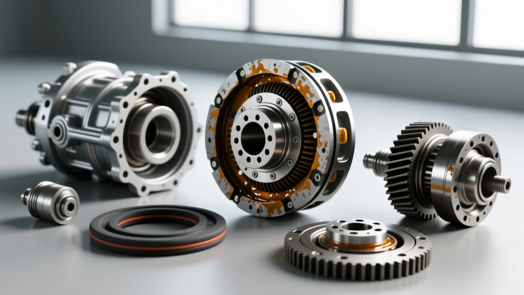
Modern 6-speed and 8-speed automatics rely heavily on the Torque Converter Clutch (TCC) for efficiency. Upgrading a 6L80 for a 700-horsepower supercharged LT1 requires a multi-clutch billet converter. Stock paper TCC friction materials will slip and burn up instantly under high line pressure. Performance units utilize carbon-Kevlar woven linings and dual or triple clutch discs to handle the immense apply pressure required for 1-2 and 2-3 shifts at WOT. Expect to invest between $1,200 and $1,800 for a high-end 6L80 billet converter. Furthermore, tuning the TCC PWM (Pulse Width Modulation) solenoid via HP Tuners is mandatory; you must increase the apply pressure tables to ensure the upgraded clutch pack locks instantly without shudder.
Torque Converter Clutch (TCC) and Lockup Upgrades
In the past, serious drag racers avoided lockup converters entirely, relying on non-lockup units (like the Powerglide or TH400) to avoid the mechanical shock of a TCC applying during a pass. However, modern performance engineering has changed this. For vehicles that see both highway cruising and track time, a lockup converter is essential to manage transmission fluid temperatures. Fluid temperatures exceeding 220°F will rapidly degrade synthetic ATF, leading to clutch glazing and valve body wear.
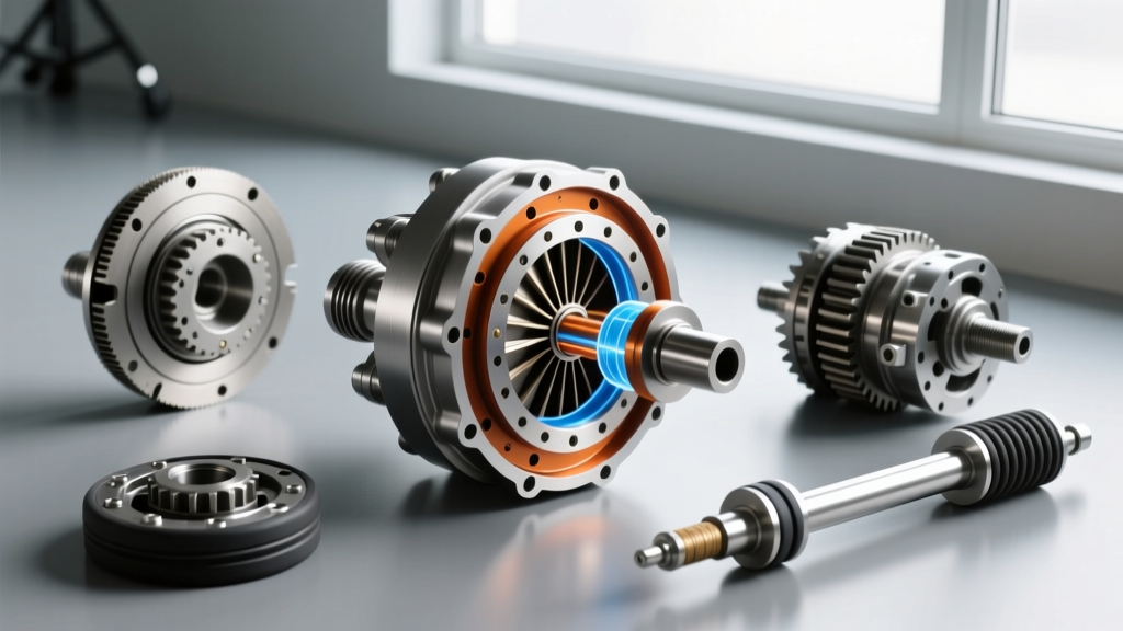
When reviewing a performance torque converter diagram for a lockup unit, look for a damper clutch assembly with heavy-duty torsion springs. These springs absorb the harmonic vibrations generated by aggressive camshafts and high-stroke crankshafts, preventing the TCC from chattering or prematurely failing. For applications exceeding 800 hp, manufacturers like Sonnax offer high-capacity TCC apply valve kits (e.g., Sonnax 34200-08K) that increase hydraulic fluid volume to the clutch piston, ensuring rock-solid lockup even under massive torque loads.
Installation and Maintenance Best Practices
To ensure your investment survives the rigors of performance driving, adhere to these strict installation protocols:
- Pre-Fill the Converter: Never install a dry converter. Pour at least 1.5 to 2 quarts of your chosen ATF (such as Mobil 1 Synthetic or Amsoil Signature) directly into the converter hub before sliding it onto the transmission input shaft.
- Verify Engagement: As you slide the converter onto the transmission, you must feel three distinct 'drops' or engagements: the input shaft, the stator support, and finally the transmission oil pump gear. If you only feel two, the pump gear will shatter on startup.
- Cooler Sizing: A tighter, higher-stall converter generates significantly more heat in the lower gears. Upgrade to a minimum 24,000 GVW auxiliary transmission cooler with a -6 AN braided line setup to maintain optimal fluid temperatures between 160°F and 185°F.
By understanding the fluid dynamics illustrated in a comprehensive torque converter diagram and matching the stall speed, fin angles, and clutch materials to your specific engine combination, you transform your automatic transmission from a parasitic weak point into a devastatingly effective performance weapon.