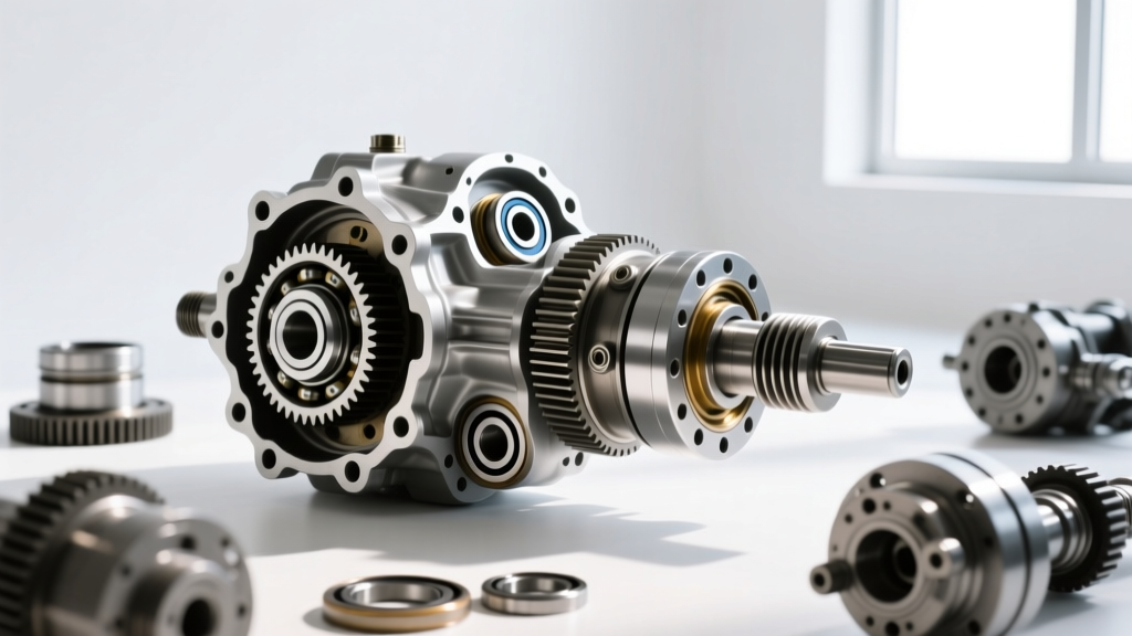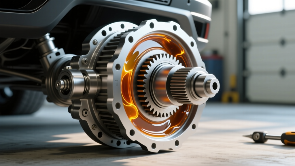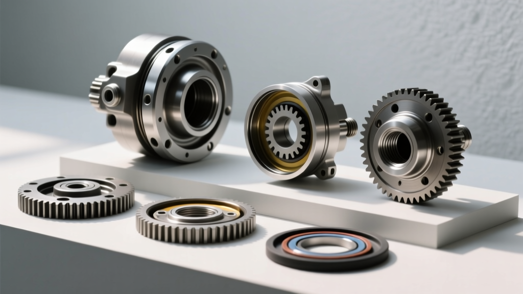
As we navigate through 2026, the vast majority of Lexus LX470s and their Toyota 100-Series Land Cruiser siblings are pushing well past the 20-year and 200,000-mile marks. While the 8-inch (200mm) semi-floating rear axle is legendary for its durability, the factory electronic locking mechanism is not immune to wear. Whether you are upgrading to 4.88 ring and pinion gears for larger tires, fixing a persistent fluid leak, or diagnosing the infamous flashing locker light, a complete teardown is often required.
Rebuilding the LX470 differential lock system is not merely about swapping bearings; it demands precise measurement of pinion depth, strict adherence to rotating preload specifications, and careful alignment of the electronic shift collar. This step-by-step guide provides the exact procedures, torque specifications, and diagnostic frameworks needed to restore your 100-series rear axle to factory perfection.
"The most common mistake DIYers make with the 100-series electronic locker is rushing the third-member removal. If you do not disconnect and carefully extract the actuator shift fork before pulling the carrier, you will snap the fork or score the locking collar, turning a standard rebuild into an expensive parts hunt." — Senior Drivetrain Technician, AutogearNexus
The Anatomy of the Toyota Electronic Locker
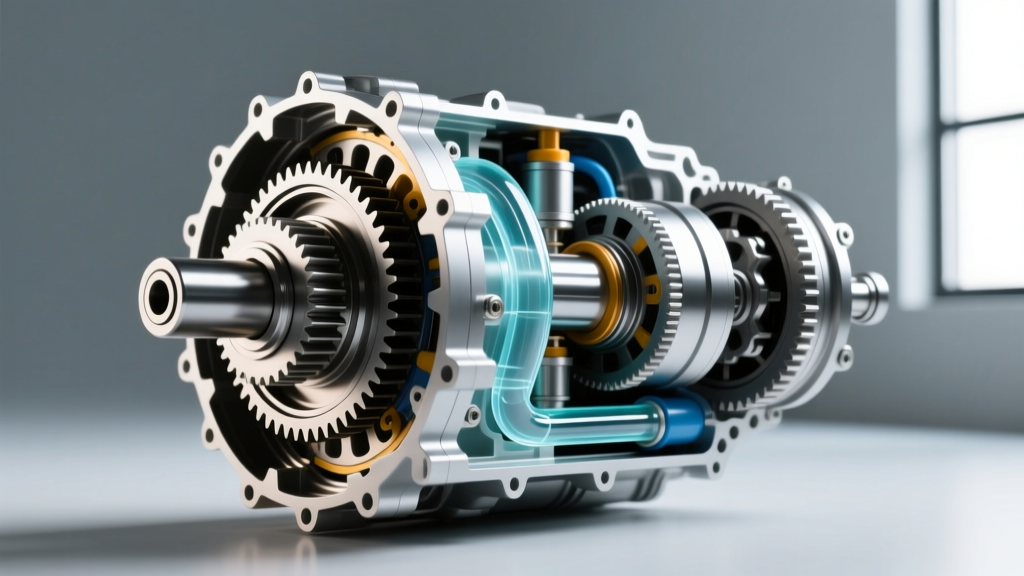
Unlike pneumatic (air) lockers that rely on compressed air to push a piston, the LX470 utilizes an electric DC motor housed in an external actuator. This motor turns a worm gear that pushes a magnetic clutch and shift fork. The fork slides a splined steel collar across the side gear, mechanically locking it to the differential carrier. When rebuilding, you must inspect not just the ring and pinion, but the physical wear on the shift fork pads and the travel limit of the collar.
Essential Tools and OEM Parts Checklist
Before draining a single drop of gear oil, ensure your workbench is equipped with the following specialized tools and components. Attempting this rebuild with standard automotive tools will inevitably lead to incorrect bearing preload and premature gear failure.
| Category | Item / Part | Specification / Notes |
|---|---|---|
| Measuring Tools | Dial Indicator & Magnetic Base | 0.0001" resolution for backlash setup |
| Torque Tools | Inch-Pound Beam Torque Wrench | Critical for pinion rotating preload |
| Bearings | Koyo Master Bearing Kit | Includes front/rear pinion & side bearings |
| Locker Specific | Actuator Shift Fork Pads | Inspect for >2.5mm thickness |
| Sealing | Toyota FIPG (Three Bond 1282B) | Part # 00295-00103 (or equivalent RTV) |
| Fluids | 75W-90 API GL-5 Gear Oil | Capacity: 3.2 Liters (3.4 Quarts) |
Step 1: Safe Extraction and Actuator Teardown
Begin by draining the rear differential. The LX470 rear diff holds approximately 3.2 liters of fluid; expect a mix of degraded oil and fine metallic paste on the magnetic drain plug. Remove the rear driveshaft and unbolt the brake calipers and ABS sensor wiring to prevent snagging.
Removing the Third Member
- Unbolt the 14mm nuts securing the third member to the axle housing. There are typically 10 nuts.
- CRITICAL STEP: Before pulling the third member outward, you must unbolt the electronic locker actuator from the side of the carrier. Gently wiggle the actuator to disengage the shift fork from the locking collar groove.
- Use a brass drift and a dead-blow hammer to tap the third member free from the housing. Do not pry between the machined mating surfaces with a screwdriver, as this will cause permanent sealing leaks.
Step 2: Pinion Depth and Bearing Preload
With the third member on the bench, remove the ring gear bolts (14mm) and separate the ring gear from the carrier. Press out the old pinion and side bearings. When installing the new Koyo bearings, use a setup bearing (a bearing with a slightly honed inner race) for the rear pinion bearing to allow for easy depth adjustments.
Setting Pinion Depth
The pinion gear has a depth variance number stamped on the face (e.g., +2, -1). This dictates the thickness of the shim placed between the rear bearing race and the carrier housing. Install the pinion without the oil seal or crush sleeve. Tighten the companion flange nut just enough to remove play, then measure the rotating torque.
- New Bearing Preload Target: 8.7 to 13.9 in-lbs (0.98 to 1.57 Nm).
- Used Bearing Preload Target: 4.3 to 6.9 in-lbs.
If the rotating torque is too low, add a thicker pinion depth shim. If it is too high, subtract shim thickness. Once the depth and rotating preload are perfect, remove the setup bearing, install the final production bearing, the new oil seal, and the new crush sleeve. Torque the final 24mm pinion nut to approximately 110 ft-lbs, checking the inch-pound rotating torque frequently until you hit the exact 8.7-13.9 in-lbs specification.
Step 3: Backlash and Locker Collar Alignment
Bolt the ring gear to the differential carrier. Apply a medium-strength thread locker to the 10 ring gear bolts and torque them to 56 ft-lbs (76 Nm) in a star pattern. Use a center punch to stake the bolt heads, preventing them from backing out under heavy axle articulation.
Dialing in Backlash
Mount the dial indicator perpendicular to the ring gear teeth. Adjust the side bearing adjuster nuts to achieve a backlash reading between 0.0051" and 0.0071" (0.13 - 0.18 mm). Ensure the side bearing preload is sufficient by verifying that the carrier requires a firm hand to rotate once the adjuster lock tabs are engaged.
The Locker Shift Fork Inspection
This is where the LX470 differential lock rebuild differs from a standard open differential. Inspect the nylon/polyurethane pads on the ends of the metal shift fork. These pads ride inside the groove of the locking collar. If the pads are worn down to less than 2.5mm, the actuator motor will push the fork, but the collar will not travel the full 4.0mm required to engage the side gear and trigger the internal limit switch. Replace the fork or weld/build up the pads with high-temp epoxy if OEM replacements are on backorder.
Step 4: Sealing, Torquing, and Fluid Fill
Clean the axle housing mating surface and the third member flange with brake cleaner. Apply a continuous 3mm bead of Toyota FIPG (or high-quality grey RTV) to the third member flange, ensuring you circle all the stud holes to prevent oil from weeping past the threads.
- Carefully lower the third member into the housing, ensuring the pinion gear does not chip the freshly applied RTV.
- Install the 14mm nuts and torque them to 27 ft-lbs (37 Nm) in a crisscross pattern.
- Reattach the locker actuator. Ensure the shift fork perfectly seats into the collar groove before tightening the actuator housing bolts to 18 ft-lbs.
- Fill the differential through the top fill plug with 3.2 Liters of 75W-90 API GL-5 gear oil until it reaches the bottom of the fill hole threads.
Troubleshooting the "Flashing Locker Light"
Post-rebuild, the most common issue LX470 owners face is the dashboard locker light flashing indefinitely when the button is pressed. According to drivetrain diagnostics data aggregated from IH8MUD technical archives, a flashing light indicates that the ECU has not received the "locked" signal from the actuator limit switch within the programmed time limit.
Diagnostic Checklist for Flashing Light:
- Cold Fluid Viscosity: 75W-90 GL-5 can be highly viscous in freezing temperatures. The thick oil can prevent the shift collar from sliding quickly enough. Drive the vehicle for 10 minutes to warm the axle fluid, then retry.
- Shift Fork Pad Wear: As mentioned in Step 3, worn pads result in incomplete collar travel. The collar locks the axle mechanically, but falls 1mm short of depressing the limit switch plunger.
- Limit Switch Failure: The microswitch inside the actuator housing is exposed to metallic dust and gear oil vapor. If the switch is stuck open, the ECU will never see the ground signal. Test the switch with a multimeter for continuity when the plunger is depressed.
- ECU Reset Procedure: Sometimes the ECU logs a fault code. Disconnect the negative battery terminal for 15 minutes, or pull the "DIFF LOCK" fuse in the engine bay fuse box to reset the actuator logic board.
For those sourcing specialized actuator components or upgraded heavy-duty ring and pinion sets, reputable 100-series vendors like Slee Offroad and official Toyota Technical Information System (TIS) wiring diagrams remain the gold standard for verifying pinout voltages and part supersessions.
By adhering strictly to these torque specifications, clearances, and diagnostic protocols, your LX470 differential lock will engage seamlessly on the trail and provide thousands of miles of reliable, quiet operation on the highway.