The Anatomy of PTO Clutch Failures in Commercial Fleets
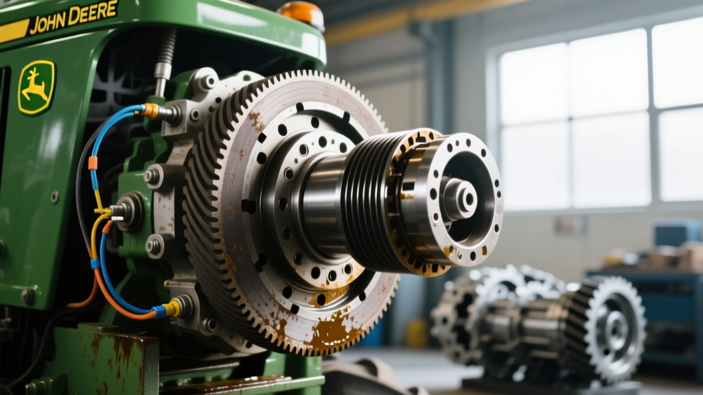
Commercial landscaping fleets and agricultural operations rely heavily on the Power Take-Off (PTO) system to drive rotary decks, snow blowers, and brush hogs. When a PTO clutch John Deere owners depend on begins to fail, the resulting downtime can cost hundreds of dollars per day in lost productivity. In heavy-duty commercial vehicles like the John Deere Z994R Z-Trak, 1025R Sub-Compact, or the 3032E Compact Utility Tractor, the electromagnetic clutch operates under extreme thermal and mechanical stress. Unlike light-duty residential models, commercial clutches must endure continuous engagement cycles, high-ambient heat, and severe shock loads from striking hidden debris.
Diagnosing clutch slipping, chatter, or complete disengagement requires a systematic approach that separates electrical deficiencies from mechanical wear. Furthermore, upgrading to high-torque aftermarket units can significantly extend service intervals and improve heavy-load performance. This guide provides a master-level diagnostic protocol and performance upgrade matrix for fleet technicians and owner-operators navigating the 2026 landscaping season.
Symptom Mapping: Identifying the Root Cause of Slipping and Chatter
Before tearing into the wiring harness or dropping the clutch assembly, technicians must accurately map the symptoms to their underlying failure modes. Heavy-duty PTO clutches typically exhibit three primary failure signatures:
- Slipping Under Load: The engine RPM remains steady, but blade or implement speed drops when encountering thick brush or wet grass. This is almost exclusively a mechanical issue caused by an excessive air gap, glazed friction surfaces, or oil contamination from a failing crankshaft main seal.
- Delayed or Sluggish Engagement: The switch is flipped, but the clutch takes 2 to 4 seconds to fully lock. This indicates a weak magnetic field, usually stemming from voltage drop across corroded connectors, a failing relay, or an out-of-spec air gap that prevents the armature from pulling in quickly.
- Thermal Shutdown (Mid-Operation Disengagement): The PTO disengages after 20 to 30 minutes of heavy use and will not re-engage until the unit cools. Modern commercial clutches feature an embedded thermal cutoff switch (typically rated for 180°C / 356°F). If the clutch overheats due to poor ventilation, belt slippage, or continuous micro-slipping, the thermal switch breaks the circuit to prevent the coil from melting.
Electrical Diagnostics: Beyond the Basic 12V Test
Fleet technicians often make the mistake of simply checking for 12 volts at the clutch pigtail. However, a heavy-duty PTO clutch requires high amperage to generate the necessary magnetic flux. A circuit can show 12V under no-load conditions but drop to 9V when the clutch engages due to high resistance.
Coil Resistance Testing
Disconnect the clutch harness and set your multimeter to the Ohms (Ω) setting. Measure the resistance across the two clutch terminals. For most John Deere heavy-duty applications (and equivalent Warner Electric or Ogura replacements), the coil resistance should read between 1.8 and 2.4 ohms at 75°F (24°C). If the reading is below 1.5 ohms, the coil has internal shorted windings and will draw excessive amperage, melting the wiring harness. If the reading is infinite (OL), the internal thermal fuse or coil wire has snapped.
Voltage Drop and Relay Upgrades
With the engine running at operating RPM (alternator outputting peak voltage), measure the voltage directly at the clutch connector while the PTO is engaged. You must see a minimum of 13.8V to 14.4V. If voltage is low, perform a voltage drop test across the PTO relay and safety interlock switches. OEM 30-amp relays are notorious for internal pitting in commercial environments. Upgrading the OEM relay to a 50-amp heavy-duty automotive relay with a 10-gauge pigtail bypass is a standard fleet upgrade that eliminates voltage starvation and extends coil life.
Mechanical Calibration: The Critical Air Gap Measurement
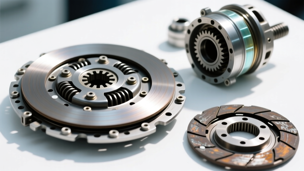
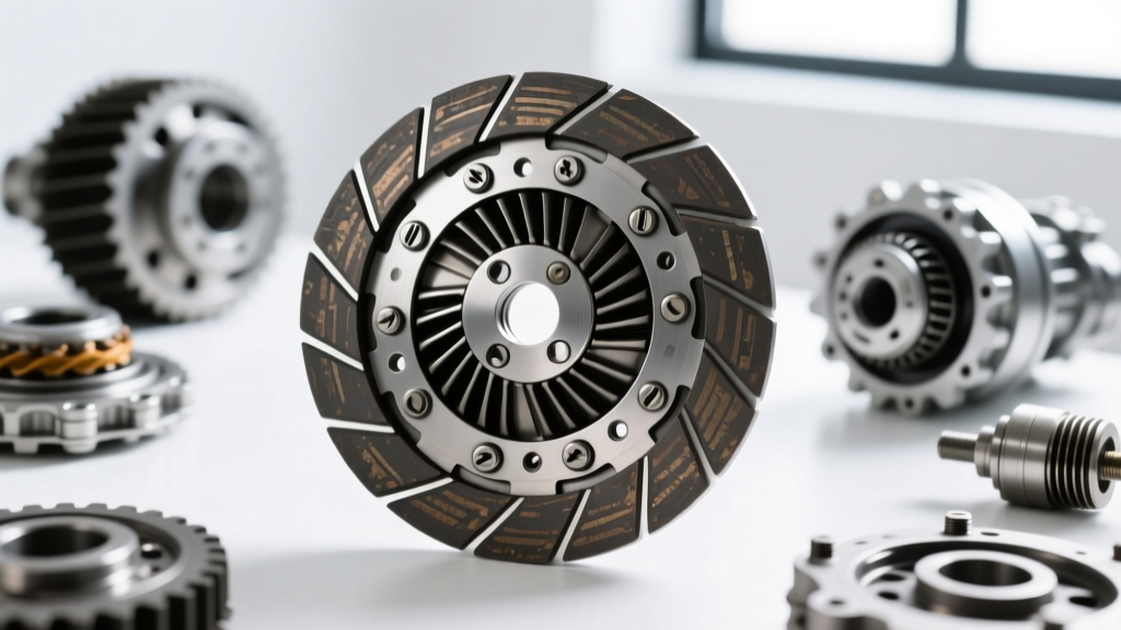
The air gap is the distance between the clutch armature (the rotating friction plate) and the rotor (the electromagnet housing). As the friction material wears down over hundreds of operating hours, this gap widens. Once the gap exceeds the magnetic field's effective pull range, the clutch will slip, generate massive heat, and eventually burn out the coil.
For most 5/8-inch and 7/8-inch shaft John Deere PTO clutches, the factory air gap specification is 0.018 to 0.024 inches.
- Measurement: Use a feeler gauge inserted through the inspection slots or between the armature and rotor. Check at three equidistant points around the circumference to ensure the armature is not warped.
- Adjustment (Shim Style): If the gap exceeds 0.025 inches, remove the clutch, disassemble the armature, and remove one or more internal spacer shims to tighten the gap back to 0.020 inches.
- Adjustment (Set-Screw Style): Some Ogura and Warner Electric models use a set-screw and nut mechanism on the armature hub. Loosen the locknut and turn the adjustment nut until the proper drag is felt on the feeler gauge, then re-torque the locknut.
Heavy-Duty Upgrade Matrix: OEM vs. Aftermarket Performance
When an OEM John Deere clutch fails in a severe-duty application, replacing it with another OEM unit may result in a repeat failure if the operating conditions exceed the unit's thermal limits. Upgrading to a purpose-built commercial clutch from Warner Electric or Ogura Industrial provides higher static torque ratings and superior heat dissipation. Below is a comparison matrix for common 7/8-inch shaft applications found on mid-size commercial Z-Traks and compact tractors.
| Clutch Model / Brand | Static Torque (lb-ft) | Max Amp Draw (12V) | Thermal Protection | Est. Price (USD) | Best Application |
|---|---|---|---|---|---|
| John Deere OEM (RE532920) | 85 - 100 | 3.5A - 4.2A | Standard 180°C Cutoff | $380 - $450 | Standard Ag & Light Commercial |
| Warner Electric (5218-751-003) | 125 - 140 | 4.5A - 5.0A | High-Temp Epoxy Coil | $290 - $340 | Heavy Brush Mowing, Snow Blowers |
| Ogura (STC2.4 Series) | 135 - 150 | 4.8A - 5.2A | Integrated Thermal Switch | $310 - $360 | High-Inertia Decks, Continuous PTO |
As noted in John Deere Technical Publications, when upgrading to a higher amperage aftermarket clutch, fleet managers must verify that the stator/alternator on the engine can support the increased electrical load without draining the battery during low-RPM operations.
Precision Installation and Torque Specifications
Improper installation is the leading cause of premature PTO clutch bearing failure and crankshaft damage. The clutch relies on a precision interference fit and exact torque values to transfer shock loads away from the crankshaft threads.
Shaft Preparation and Anti-Seize
Never install a new PTO clutch on a rusted or scored crankshaft. Use a wire wheel and emery cloth to polish the shaft. Apply a thin layer of copper-based anti-seize compound to the crankshaft surface to prevent galvanic corrosion and ensure the clutch can be removed during future services. Do not get anti-seize on the friction surfaces or the belt pulley.
Crankshaft Bolt Torque Specs
The center retaining bolt must be torqued to exact specifications to prevent the clutch from walking on the shaft, which will destroy the internal rotor bearing and ruin the engine's main seal. Use a calibrated torque wrench and follow these general heavy-duty specs:
- 5/8-inch Shaft (3/8-16 or 7/16-20 bolt): 55 to 65 ft-lbs.
- 7/8-inch Shaft (5/8-18 bolt): 95 to 110 ft-lbs.
- 1-1/8-inch Shaft (3/4-16 bolt): 140 to 160 ft-lbs.
Always apply a medium-strength threadlocker (such as Loctite 242) to the center bolt threads if the OEM manual specifies it, but never apply threadlocker to the crankshaft splines or tapers.
The Burnishing Process: A Mandatory Fleet Protocol
A critical step often skipped by commercial technicians is the burnishing (or seating) process. New PTO clutches have microscopic machining marks on the friction surfaces. If subjected to full load immediately, these high spots will overheat, glaze the friction material, and permanently reduce the clutch's torque capacity.
Burnishing Procedure:
- Install the clutch and set the air gap to factory specs.
- Start the tractor/mower and run the engine at low idle (PTO shaft speed roughly 1,200 - 1,500 RPM).
- Engage the PTO for 3 to 5 seconds, then disengage for 5 seconds.
- Repeat this cycle 50 to 100 times. This generates controlled friction heat, mating the armature to the rotor surface without causing thermal shock.
- After burnishing, re-check the air gap, as the initial seating will often reduce the gap by 0.002 to 0.004 inches.
Preventative Maintenance for Maximum Uptime
To maximize the lifespan of heavy-duty PTO clutches, fleet maintenance schedules must include belt tension verification and deck cleaning. An over-tensioned drive belt places severe radial loads on the clutch's internal ball bearing, leading to premature mechanical failure. Conversely, a loose belt causes micro-slipping at the pulley, generating heat that transfers directly into the clutch rotor. Finally, blowing out grass clippings and debris from the clutch cooling fins daily is mandatory; blocked fins will cause the thermal cutoff switch to trip continuously, mimicking an electrical failure and leading to unnecessary part replacements.