The Anatomy of a Drag-Prepped Jockey Shifter and Hand Clutch System
As we navigate the 2026 drag racing and pro-touring seasons, space constraints and weight distribution priorities in modern tube-chassis builds have driven a surge in unconventional actuation setups. Adapting a jockey shifter with hand clutch kit is no longer just a niche solution for vintage hot rods or custom motorcycles; it is a highly engineered requirement for Super Street, Pro Mod, and specialized drag buggy applications where foot pedals are eliminated to accommodate steering column geometry, brake chutes, or trans-brake solenoids.
However, replacing a traditional foot-operated clutch pedal and floor-mounted shifter with a hand-actuated hydraulic lever and a pedestal-mounted jockey shifter introduces severe mechanical leverage deficits and routing complexities. A standard foot pedal yields a 4:1 to 6:1 mechanical advantage. A dash-mounted hand lever typically offers only 1.5:1 to 2:1. If your installation does not account for this loss of leverage, or if your shift cable routing violates minimum bend radius tolerances, your drivetrain will suffer from catastrophic clutch drag, missed shifts, and premature component failure. This guide provides the exact engineering parameters, torque specifications, and component pairings required to execute this swap flawlessly.
Pre-Installation: Matching the Clutch Disc and Pressure Plate
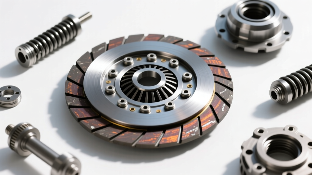
Because a hand clutch lever limits the physical force a driver can apply (typically capping around 120–150 lbs of grip force compared to the 300+ lbs a leg can generate), you cannot simply bolt on a 3,200-lb clamp load sintered iron pressure plate and expect modulation. You must pair your hand clutch master cylinder with a clutch disc and pressure plate engineered for lower hydraulic volume requirements while maintaining high torque capacity.
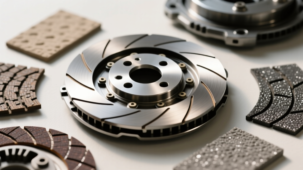
For engines producing 600 to 900 horsepower, a twin-disc setup utilizing a carbon-metallic or Kevlar friction material is ideal. Carbon-metallic discs offer a progressive engagement curve that forgives the abrupt nature of hand-lever releases, whereas sintered iron will instantly shock the driveline, leading to U-joint failures or ring gear shearing on the rear differential.
| Friction Material | Torque Capacity | Modulation Profile | Ideal Hand Clutch Bore |
|---|---|---|---|
| Organic / Kevlar Blend | 450 - 650 lb-ft | Highly Progressive (Smooth) | 3/4" or 7/8" Master |
| Carbon-Metallic | 700 - 1,100 lb-ft | Moderate Bite (Forgiving) | 5/8" or 3/4" Master |
| Sintered Iron (Full) | 1,200+ lb-ft | Instant Lock (Aggressive) | Not Recommended for Hand |
Note: Always verify clamp load requirements with manufacturers like McLeod Racing or Ram Clutches before finalizing your hydraulic ratio.
Hydraulic Sizing for Hand-Actuated Master Cylinders
The most critical failure point in a hand clutch installation is improper master cylinder bore sizing. To generate sufficient hydraulic line pressure to actuate a hydraulic throwout bearing (HTOB) or a heavy-duty clutch fork without exhausting the driver's hand, you must decrease the master cylinder bore size.
A standard 7/8" bore master cylinder requires roughly 35% more hand-grip force to move the same volume of fluid as a 5/8" bore cylinder. For a hand clutch kit operating a McLeod or Tilton HTOB on a 2,400-lb pressure plate, a 5/8" bore master cylinder is the industry standard. This increases the travel of the hand lever but drastically reduces the physical effort required to disengage the clutch discs.
Calculating HTOB Air Gap and Stroke
When using a hydraulic throwout bearing, you must set the air gap between the bearing face and the pressure plate fingers. Unlike a mechanical fork, an HTOB has no external adjuster once the bellhousing is bolted down.
- Measure Free Travel: Use a dial indicator to measure the total stroke of the HTOB piston. Typical Tilton 6000-series bearings offer 0.450" of total travel.
- Set the Air Gap: You must maintain a 0.100" to 0.150" air gap to prevent the bearing from pre-loading against the clutch fingers, which will cause the clutch to slip under high RPM and burn out the friction discs.
- Shim the Master Cylinder: If the hand lever bottoms out before the clutch fully disengages, add shims behind the master cylinder pushrod or adjust the pedal stop (lever stop) to maximize fluid displacement.
Mounting the Jockey Shifter: Driveline Alignment and Cable Routing
A jockey shifter—typically a ratcheting pedestal shifter like the B&M Pro Ratchet or a custom cable-driven gated lever—relies entirely on push-pull shift cables. The internal friction of these cables dictates shift feel and reliability. According to technical documentation from B&M Racing, violating the minimum bend radius of a shift cable will cause the internal Teflon liner to gall, leading to a seized cable mid-pass.
- Minimum Bend Radius: Never bend a standard 33-series or 64-series shift cable tighter than a 4.0-inch radius. For tight firewall or transmission tunnel clearances, use a 90-degree cable boot adapter rather than forcing a bend.
- Conduit Support: The outer cable housing must be rigidly mounted within 6 inches of the shifter base and within 4 inches of the transmission shift arm. Use billet aluminum cable clamps and torque them to 15 ft-lbs to prevent housing compression during aggressive 2-3 upshifts.
- Neutral Safety Switch Integration: Most jockey shifters do not feature an integrated neutral safety switch. You must wire a micro-switch to the transmission shift arm or utilize a neutral safety switch integrated into the hand clutch lever to prevent the starter from engaging while the clutch discs are engaged.
Bleeding Protocols and Critical Torque Specifications
Hand clutch systems are notorious for trapping micro-bubbles in the master cylinder because the lever is often mounted horizontally on a dash or steering column, creating a high-point trap for air. Vacuum bleeding from the HTOB bleeder screw is insufficient. You must reverse-bleed the system, pushing fluid from the transmission HTOB up to the hand lever reservoir.
Master Installation Torque Chart
| Component | Hardware / Fitting | Torque Specification |
|---|---|---|
| Master Cylinder Flange | 1/4"-28 Stainless Bolts | 12-15 ft-lbs (use Loctite 243) |
| AN-3 Clutch Line Fitting | AN-3 Aluminum Nut | 8-10 ft-lbs (Do not overtighten) |
| HTOB Feed Line Adapter | 1/8" NPT to AN-3 | 15-18 ft-lbs (with PTFE tape) |
| Jockey Shifter Base Plate | 5/16"-18 Grade 8 Bolts | 25-30 ft-lbs |
| Bellhousing to Block | 7/16"-14 Bolts | 50-55 ft-lbs (Verify TIR < 0.005") |
Reference the Tilton Engineering Technical Library for specific reverse-bleeding syringe procedures and HTOB break-in protocols.
Troubleshooting Common Engagement and Shift Rail Issues
Even with precision installation, adapting a hand-operated system to an automotive transmission (such as a TH400 with a manual valve body or a Muncie M22) presents unique diagnostic challenges. Use this expert framework to isolate drivetrain faults:
- Symptom: Clutch Dragging During Shifts (Grinding Gears)
Diagnosis: Insufficient fluid displacement or air in the hand lever reservoir. Because hand levers have short strokes, a 3% air volume in the line will result in a 15% loss of throw at the HTOB. Perform a secondary reverse-bleed and verify the HTOB air gap has not closed due to clutch disc wear. - Symptom: Jockey Shifter Feels 'Notchy' or Binds in 2nd/3rd Gear
Diagnosis: Shift cable misalignment or bellhousing runout. If the bellhousing is offset by more than 0.005" Total Indicated Runout (TIR), the transmission input shaft will bind in the pilot bearing. This side-loads the shift rails inside the transmission, making the jockey shifter feel physically jammed. Use a dial indicator on the bellhousing bore and install offset dowel pins if necessary. - Symptom: Hand Lever Returns Slowly or Sticks
Diagnosis: The return spring on the clutch fork or the internal HTOB return spring is insufficient to push the fluid back up the line to the hand lever. Install a 150-lb external return spring on the clutch fork pivot ball to ensure the master cylinder piston fully reseats, preventing the clutch from riding the fingers.
Final Alignment and Track-Side Verification
Before loading the vehicle onto the trailer, perform a static modulation test. With the rear wheels off the ground and the engine idling, squeeze the hand clutch lever and pull the jockey shifter through the gears. The engagement point should occur at approximately 60% of the hand lever's total travel. If it engages at 20%, your HTOB is pre-loaded and will destroy the carbon-metallic discs under load. If it engages at 95%, you lack the stroke to fully disengage the clutch at the top of the tree. Dial in your pushrod length, verify your AN fitting torque specs, and ensure your shift cables are routed with sweeping, unrestricted bends. Mastering these installation nuances is the difference between a podium finish and a DNF in the pits.