The Diagnostic Challenge of Intermittent Clutch Faults
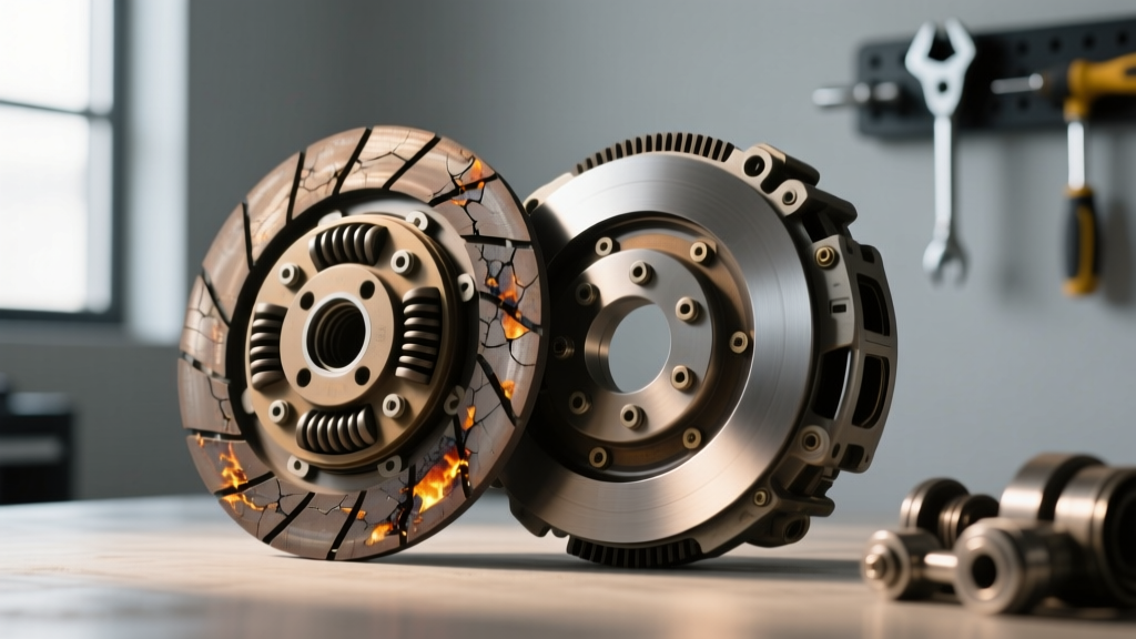
Hard clutch failures are straightforward: a shattered pressure plate diaphragm, a completely blown slave cylinder seal, or a friction disc worn down to the rivets. Intermittent clutch problems, however, are the bane of modern manual transmission diagnostics. A vehicle that shifts perfectly cold but grinds going into reverse when hot, or a pedal that occasionally sticks to the floorboard during high-RPM shifts, often sends technicians down a path of unnecessary transmission removals. In many of these ghost-fault scenarios, the root cause lies not inside the bellhousing, but at the driver's feet. Specifically, the nuanced science of adjusting hydraulic clutch pedal geometry and pushrod clearance is frequently overlooked.
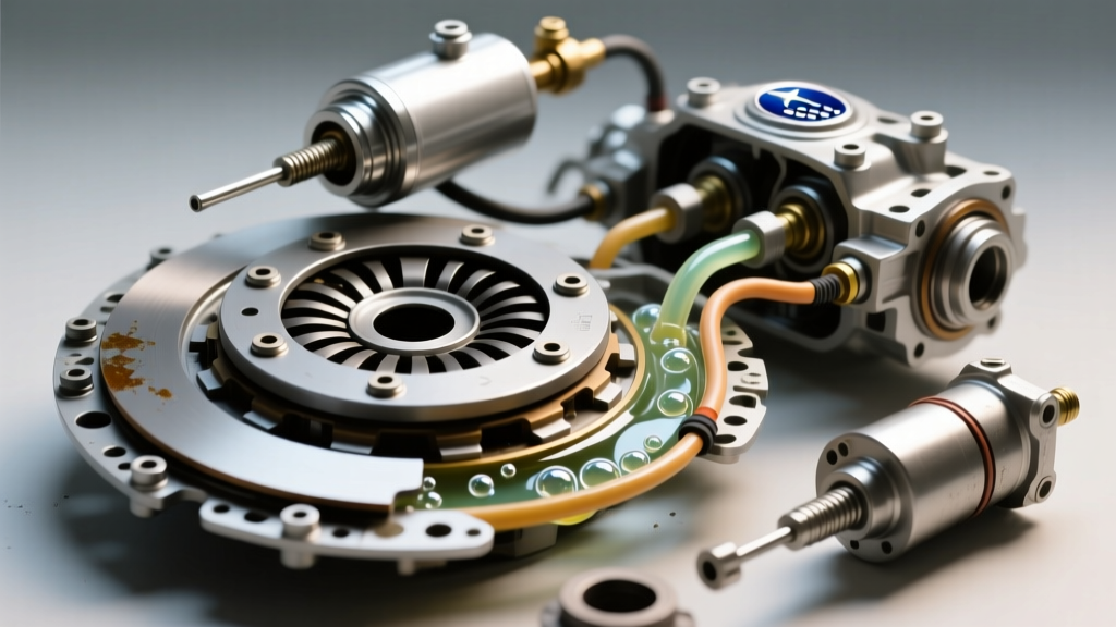
Modern manual setups, ranging from the Tremec T56 Magnum to the Ford MT82 and Porsche G50 transaxles, rely on precise hydraulic volume displacement. When a hydraulic system suffers from intermittent disengagement or engagement faults, the friction assembly is often wrongly condemned. According to technical bulletins from Schaeffler REPXPERT, up to 30% of premature clutch replacement claims are actually rooted in improper hydraulic adjustment, fluid hygroscopy, or master cylinder compensating port blockage.
Intermittent Symptom Matrix: Mapping Inconsistent Behavior
Before tearing into the drivetrain, map the exact environmental and operational triggers of the fault. Use the diagnostic matrix below to isolate the variable causing the intermittent behavior.
| Intermittent Symptom | Primary Trigger | Probable Root Cause | Verification Method |
|---|---|---|---|
| Grinds into reverse only when hot | Thermal Expansion | Master cylinder cup seal bypassing due to heat/wear | Measure slave stroke cold vs. hot; check fluid temp |
| Pedal sticks to floor at high RPM | Centrifugal Force / Flow | Weak pedal return spring or over-center master pushrod | Inspect pedal bumper; verify pushrod free-play |
| Slips under heavy load, then grips | Hydraulic Pressure | Blocked compensating port; fluid cannot return to reservoir | Check reservoir fluid level rise during pedal actuation |
| Engagement point moves up and down | Air / Vapor Lock | Micro-leak at slave cylinder pushrod seal drawing air | Pressure bleed at 30 PSI; inspect for micro-bubbles |
Why Adjusting Hydraulic Clutch Pedal Free-Play is Critical
The phrase 'adjusting hydraulic clutch pedal' often confuses DIYers and junior technicians because many modern OEM vehicles feature 'self-adjusting' hydraulic systems. However, self-adjusting only refers to the automatic wear compensation of the clutch disc via a concentric slave cylinder (CSC) or a self-adjusting pressure plate. It does not negate the need for precise pushrod-to-piston clearance at the master cylinder.
Pushrod Clearance and Compensating Port Blockage
Inside the clutch master cylinder, a tiny compensating port connects the high-pressure chamber to the fluid reservoir. When the pedal is fully released, the master cylinder piston must retract completely past this port. If the pushrod is adjusted too tightly (zero free-play), the piston remains slightly depressed. As the brake/clutch fluid heats up and expands, the trapped fluid has nowhere to go, effectively applying the clutch slightly. This causes intermittent slipping that disappears once the fluid cools and contracts. Conversely, excessive free-play results in a low engagement point and intermittent failure to fully disengage the clutch, leading to gear clash.
Step-by-Step: Adjusting Hydraulic Clutch Pedal Mechanisms
Whether you are working with an adjustable aftermarket unit from Wilwood Engineering or shimming an OEM Girling master cylinder, the target specifications remain universally critical.
- Measure Existing Free-Play: Using a steel ruler, measure the pedal pad travel before you feel hydraulic resistance. Target specification is typically 0.50 to 0.75 inches (12mm to 19mm).
- Verify Pushrod-to-Piston Clearance: For adjustable pushrods, the clearance between the pushrod tip and the master cylinder piston must be exactly 0.020 to 0.040 inches (0.5mm to 1.0mm). This ensures the piston fully uncovers the compensating port.
- Adjust the Pushrod: Loosen the jam nut on the master cylinder pushrod. Turn the rod to achieve the 0.020-inch clearance. Use a feeler gauge through the reservoir access or via the master cylinder mounting flange if accessible.
- Adjust the Pedal Stop/Bumper: The pedal must rest against the factory rubber bumper or an adjustable firewall stop. If the bumper is crushed or missing, the pedal will over-travel forward, altering the pushrod geometry. Replace with a new OEM bumper or install a CNC-machined firewall stop.
- Torque Specifications: When reinstalling the master cylinder to the firewall or bracket, torque the mounting nuts to 15-20 Nm (11-15 lb-ft). Over-torquing can warp the aluminum or plastic bore, causing the piston to bind intermittently.
Thermal Bypass: The 'Cold vs. Hot' Intermittent Slip
One of the most misdiagnosed intermittent issues is the 'cold vs. hot' slip. A vehicle might hold 600 lb-ft of torque on the dyno when cold, but slip on the highway after 45 minutes of driving. While a failing pressure plate is possible, hydraulic thermal bypass is the more frequent culprit.
DOT 3 and DOT 4 brake fluids are highly hygroscopic. Over three to four years, the fluid in the clutch line can absorb up to 3% to 4% water by volume. This drastically lowers the fluid's boiling point. Furthermore, water contamination accelerates the degradation of the EPDM rubber cup seals inside the master cylinder. When the engine bay heats up, the master cylinder body expands slightly. A worn cup seal that holds pressure perfectly when cold will allow fluid to bypass the seal and return to the reservoir when hot, resulting in a pedal that slowly sinks to the floor at stoplights or a clutch that intermittently slips under load.
The Fix: Flush the system with high-quality, low-viscosity DOT 4 or DOT 5.1 fluid. If the master cylinder has over 80,000 miles and exhibits thermal bypass, rebuilding the bore is rarely successful due to microscopic scoring. Replace the master cylinder assembly.
Hydraulic Component Replacement: Specs and Pricing
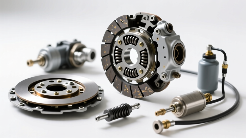
When adjusting the hydraulic clutch pedal fails to resolve the intermittent fault, component replacement is required. Always match the master cylinder bore size to the slave cylinder volume. Swapping a 5/8-inch bore master for a 3/4-inch bore will increase pedal effort by 28% and decrease stroke length, often causing incomplete disengagement on high-clamp-load aftermarket pressure plates.
- OEM Master/Slave Assemblies (e.g., Honda K-Series, Ford MT82): Typically range from $120 to $250. These feature non-adjustable, clipped-in pushrods. Adjustment requires replacing the pedal assembly or adding shims behind the master cylinder.
- Aftermarket Performance Kits (e.g., McLeod, Tilton): Ranging from $350 to $650. These feature billet aluminum bodies, adjustable pushrods, and braided stainless lines. They require meticulous setup of the 0.020-inch piston clearance.
- LuK / Sachs RepSet Pro (Includes CSC): $250 to $450. When replacing a Concentric Slave Cylinder, it is mandatory to pre-fill the CSC bore with fluid before installation and use a pressure bleeder. Vacuum bleeding often fails to evacuate the air trapped in the CSC accumulator spring, leading to intermittent sponginess.
Final Verification Protocol
After adjusting the hydraulic clutch pedal and bleeding the system, perform the 'Block Test'. With the engine running, press the clutch pedal to the floor and shift into first gear. Hold the pedal down for 30 seconds. If the transmission begins to creep or gear whine increases, the master cylinder is internally bypassing. Next, perform 20 rapid, full-stroke pedal pumps to simulate high-RPM shifting. If the pedal fails to return to the upper stop instantly, inspect the return spring tension and ensure the clutch fork pivot ball inside the bellhousing is not binding. For comprehensive drivetrain integration guidelines, refer to the Tremec Technical Support documentation regarding hydraulic throw-out bearing setups and bellhousing clearances.
Intermittent clutch problems are rarely magic; they are simply physics waiting to be measured. By mastering the exact specifications of hydraulic pedal geometry, you can save thousands of dollars in unwarranted transmission pulls and restore factory-crisp shift quality.