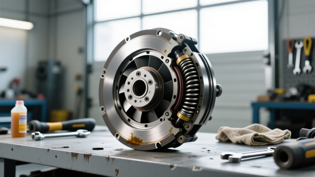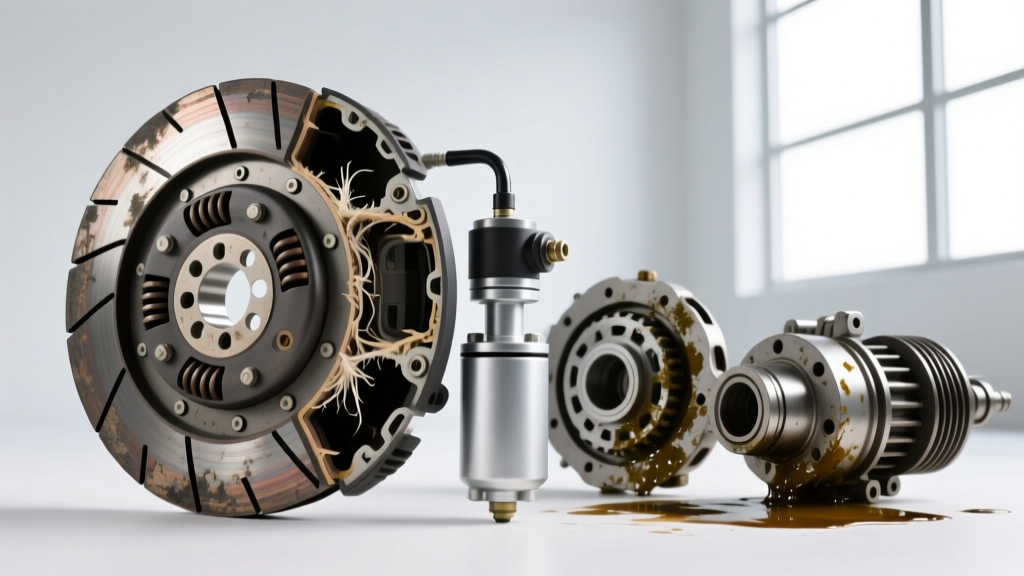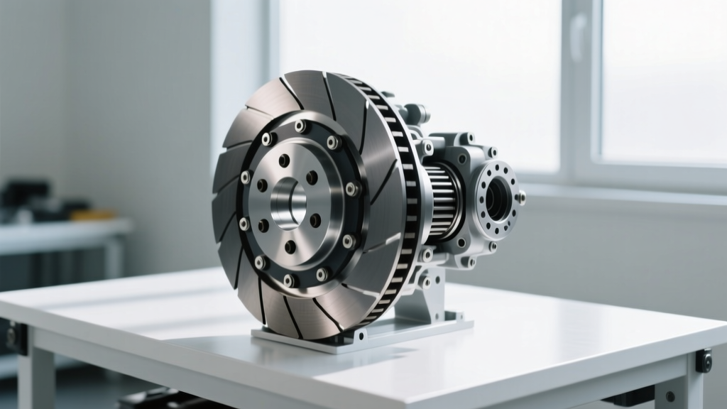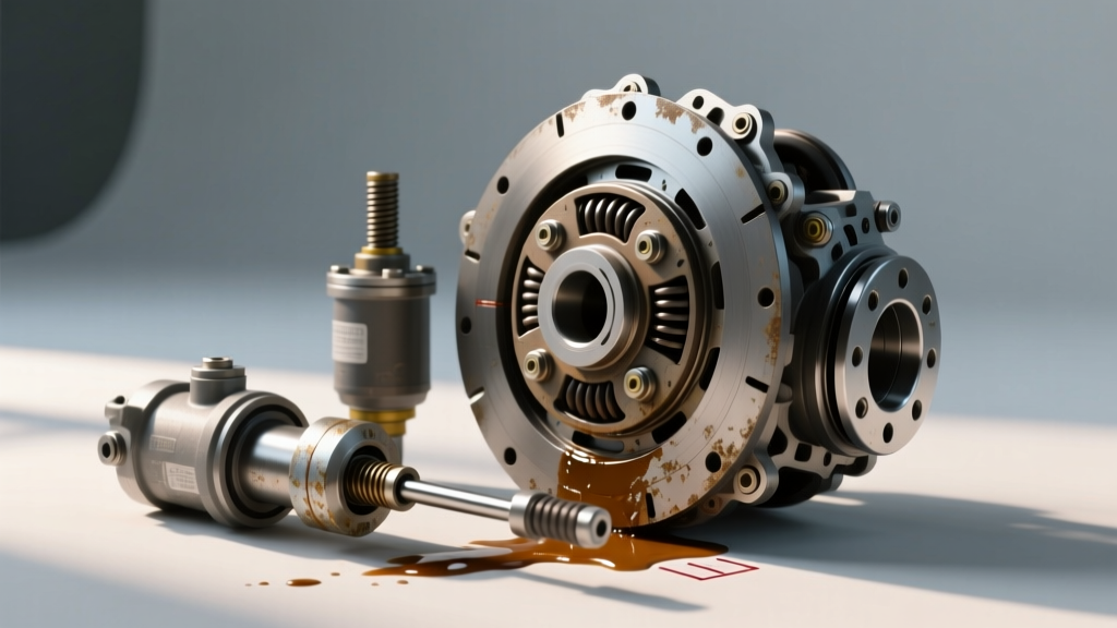
One of the most common and costly misdiagnoses in manual transmission service is condemning the throw-out bearing based on noise or engagement issues alone. Before committing to a labor-intensive clutch release bearing repair—which typically requires dropping the transmission and costs between $1,400 and $2,800 in 2026—technicians must perform a rigorous hydraulic clutch system diagnosis. A failing hydraulic circuit frequently mimics the symptoms of a worn release bearing, and in many cases, hydraulic drag is the root cause of premature bearing failure. This preventive maintenance guide outlines the exact diagnostic procedures, specifications, and fluid dynamics required to accurately isolate hydraulic faults from mechanical bearing wear.
The Physics of Hydraulic Drag on Release Bearings
The clutch release bearing (or throw-out bearing) is designed to spin only during clutch disengagement. In modern manual transmissions, hydraulic pressure from the master cylinder actuates either an external slave cylinder (e.g., GM T56 Magnum) or an internal Concentric Slave Cylinder (CSC), such as those found in the Ford MT-82 or Porsche G50 transaxles. If the hydraulic system fails to fully retract, or if internal bypass in the master cylinder creates residual line pressure, the slave cylinder remains partially engaged. This 'hydraulic drag' forces the release bearing into constant, light contact with the clutch diaphragm spring fingers.
Over time, this constant friction generates excessive heat, degrades the bearing's internal synthetic grease, and accelerates race wear. According to technical bulletins from Schaeffler REPXPERT, up to 30% of premature release bearing failures are directly traceable to unresolved hydraulic system faults rather than defective bearing manufacturing. Diagnosing the hydraulic circuit first is the ultimate preventive measure.
Step-by-Step Hydraulic Clutch System Diagnosis
Proper diagnosis requires moving beyond a simple visual inspection for fluid leaks. You must evaluate the hydraulic system's pressure dynamics, mechanical ratios, and fluid integrity.
1. Pedal Freeplay and Pushrod Measurement
The first step in preventing unnecessary clutch release bearing repair is verifying pedal freeplay. Freeplay ensures the master cylinder piston fully retracts, uncovering the compensation port and allowing fluid to return to the reservoir. If the pushrod is misadjusted or the pedal stop is worn, residual pressure builds in the line.
- Target Freeplay: Most modern passenger vehicles require 0.40 to 0.60 inches (10-15mm) of freeplay at the pedal pad before resistance is felt.
- Master Cylinder Pushrod Clearance: Using a depth gauge, verify the clearance between the master cylinder piston and the pushrod. A clearance of 0.020 to 0.040 inches is standard. Zero clearance guarantees hydraulic drag.
2. Master Cylinder Leak-Down and Bypass Testing
Internal bypass occurs when the master cylinder's internal cup seals wear, allowing fluid to slip past the piston under pressure. This results in a pedal that slowly sinks to the floor when held down, or a clutch that fails to fully disengage, causing gear clash and forcing the driver to 'ride' the pedal, which overworks the release bearing.
- Depress the clutch pedal and hold it against the floorboard with a rigid pole or specialized pedal depressor tool.
- Apply steady pressure for 60 seconds.
- If the pedal slowly rises or the clutch begins to engage while the pedal remains pinned, the master cylinder is internally bypassing and must be replaced. Common OEM replacements include the Aisin CRT-007 for Honda K-Series applications or the LuK LMC365 for GM platforms.
3. Slave Cylinder and Line Restrictions
For external slave setups, inspect the pushrod return spring. A fatigued spring will fail to pull the slave cylinder piston back, maintaining contact with the clutch fork. For internal CSC setups, such as the Sachs SH5007 used in many Ford and BMW applications, restriction in the hard lines or a clogged banjo bolt filter can trap fluid in the slave, preventing retraction. Use a line pressure gauge adapted to the bleed screw to verify that pressure drops to 0 PSI immediately upon pedal release.
Diagnostic Decision Matrix: Hydraulic vs. Mechanical Failure
Distinguishing between a failing hydraulic system and a genuine need for clutch release bearing repair requires careful symptom analysis. Use the following matrix to guide your diagnostic conclusions.
| Symptom | Hydraulic System Fault | Mechanical Release Bearing Fault | Primary Diagnostic Action |
|---|---|---|---|
| Growling noise at idle, pedal released | Unlikely (Hydraulics disengaged) | Highly Likely (Input shaft bearing or worn release bearing riding on fingers) | Inspect bellhousing inspection cover; check input shaft endplay. |
| Squealing noise only when pedal is depressed | Possible (Slave pushrod binding) | Highly Likely (Dry bearing races under load) | Measure slave pushrod travel; listen via chassis ear near bellhousing. |
| Pedal slowly rises after being depressed | Highly Likely (Master cylinder internal bypass) | Unlikely | Pinch clutch line; if pedal still rises, replace master cylinder. |
| Difficulty engaging 1st or Reverse gear | Highly Likely (Incomplete disengagement due to air/leaks) | Possible (Worn fingers, but usually accompanied by noise) | Check fluid level, bleed system, measure fork travel. |
| Clutch chatter on takeoff | Possible (Erratic fluid pressure delivery) | Possible (Binding bearing on transmission input shaft sleeve) | Check for fluid contamination on friction disc; inspect input shaft splines. |
Advanced Bleeding Protocols for Concentric Slave Cylinders
If your diagnosis reveals air in the system or contaminated fluid, a standard gravity bleed is rarely sufficient for modern CSCs. Air becomes trapped in the high points of the internal hydraulic circuit, leading to a spongy pedal and inconsistent bearing actuation. As outlined by transmission engineering standards from TREMEC, improper bleeding is a leading cause of premature wear in high-performance manual gearboxes.
The Reverse-Pressure Bleeding Method:
For internal slaves, injecting fluid from the bleed screw upward toward the master cylinder is the most effective way to purge air. Using a pneumatic fluid evacuator/injector set to 15-20 PSI, force fresh DOT 4 LV (Low Viscosity) or DOT 5.1 fluid into the slave cylinder. This pushes air bubbles up and out through the master cylinder reservoir. Always use a diaphragm cap on the reservoir to prevent fluid from damaging the vehicle's paint. After bleeding, verify that the slave cylinder stroke meets factory specifications (e.g., 0.450 inches of travel for the GM T56 Magnum external slave).
2026 Preventive Maintenance Schedule
To maximize the lifespan of the hydraulic system and prevent a costly clutch release bearing repair, adhere to this preventive maintenance schedule. Modern synthetic hydraulic fluids degrade over time due to moisture absorption, which lowers the boiling point and promotes internal corrosion in the master and slave cylinders.
- Every 12,000 Miles / 12 Months: Inspect hydraulic fluid level and color. Fluid should be clear to light amber. Dark or cloudy fluid indicates moisture contamination or deteriorating rubber cup seals.
- Every 30,000 Miles: Perform a full hydraulic system flush using the reverse-pressure method. Replace with OEM-specified fluid (typically DOT 4 LV for European applications or standard DOT 3 for older domestic platforms).
- Every 60,000 Miles: Inspect external slave cylinder pushrod boots for tearing. Check master cylinder firewall mounting nuts for proper torque (typically 15-18 lb-ft) to prevent pedal flex and inconsistent hydraulic delivery.
- During Every Engine Oil Change: Visually inspect the bellhousing inspection cover for signs of weeping from an internal CSC. A single drop of fluid on the inspection cover warrants immediate hydraulic pressure testing.
By treating the hydraulic clutch system as a precision hydraulic circuit rather than a simple mechanical linkage, technicians and enthusiasts can accurately diagnose faults, eliminate hydraulic drag, and entirely avoid premature clutch release bearing repair. Proper diagnosis saves thousands of dollars in unnecessary transmission removal labor and ensures optimal clutch modulation and drivetrain longevity.
For further reading on manual transmission diagnostics and clutch system engineering, refer to the technical resources available via the SAE International mobility engineering database.