The Dairy Ashford Corridor: A Crucible for Hydraulic Clutches
When analyzing fleet and commuter data from the high-density transit routes of Houston's Dairy Ashford corridor, a distinct pattern emerges regarding manual transmission longevity. The relentless stop-and-go traffic, combined with extreme ambient under-hood temperatures, accelerates the degradation of hydraulic clutch components. For technicians and DIY enthusiasts studying clutch automotive Dairy Ashford repair trends, understanding the nuances of hydraulic system preventive maintenance is no longer optional—it is critical for avoiding catastrophic drivetrain failures. This 2026 preventive maintenance guide dives deep into the diagnosis, fluid dynamics, and mechanical tolerances of modern hydraulic clutch circuits.
Core Anatomy and Failure Points of the Hydraulic Circuit
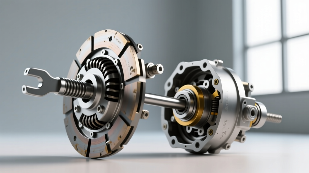
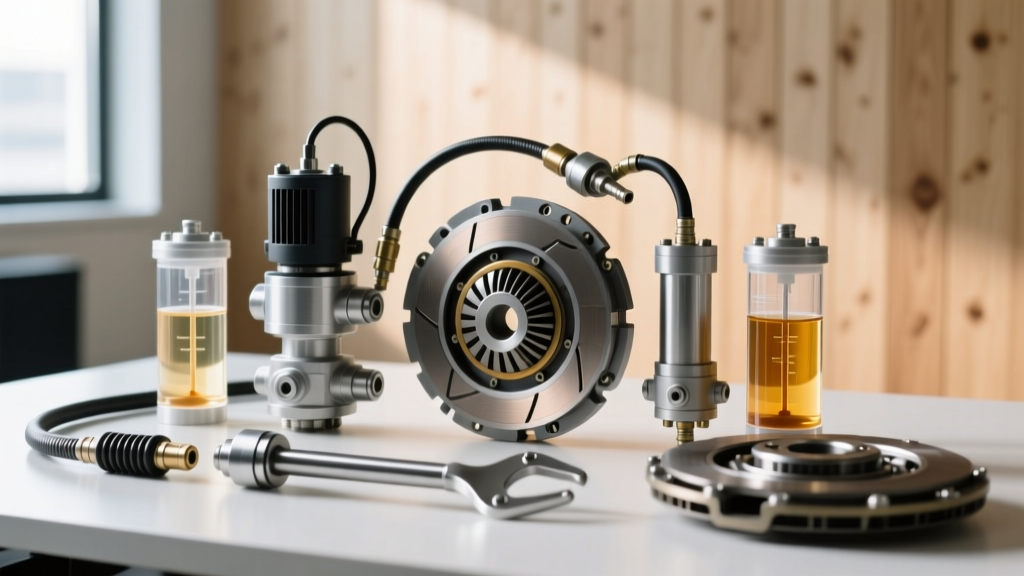
A standard hydraulic clutch system relies on Pascal's Law to multiply pedal force. The primary components include the master cylinder (MC), a hard hydraulic line, a flexible rubber hose, and the slave cylinder. Modern vehicles predominantly use one of two slave cylinder configurations:
- External Slave Cylinder (ESC): Mounted on the outside of the bellhousing, pushing a lever to engage the release bearing. Common in heavy-duty trucks and older RWD platforms.
- Concentric Slave Cylinder (CSC): A combined hydraulic cylinder and release bearing that mounts directly over the transmission input shaft. Found in 90% of modern FWD and performance RWD vehicles (e.g., ZF 6-speed and Tremec T56 Magnum applications).
Preventive diagnosis requires understanding that hydraulic failures rarely happen without warning. The most common failure mode is not a sudden line rupture, but rather internal seal degradation and fluid hygroscopic absorption, leading to a spongy pedal or incomplete disengagement.
Hydraulic Fluid Dynamics and SAE Standards
Clutch systems share fluid types with brake systems, but the thermal environment differs drastically. A brake caliper experiences extreme localized heat during braking, while a clutch master cylinder is often mounted near the engine block, and the CSC sits directly inside a bellhousing that can exceed 220°F (104°C) during heavy traffic. Because glycol-based fluids are hygroscopic (moisture-absorbing), the wet boiling point is the most critical metric for preventive maintenance.
2026 Fluid Specification Matrix
| Fluid Type | SAE / ISO Standard | Dry Boiling Point | Wet Boiling Point (3.7% H2O) | Viscosity at -40°C | Best Application |
|---|---|---|---|---|---|
| DOT 3 | SAE J1703 | 205°C (401°F) | 140°C (284°F) | 1500 mm²/s | Legacy economy vehicles |
| DOT 4 | SAE J1703 | 230°C (446°F) | 155°C (311°F) | 1800 mm²/s | Standard daily drivers, light trucks |
| DOT 4 LV (Low Viscosity) | ISO 4925 Class 6 | 260°C (500°F) | 180°C (356°F) | 700 mm²/s | 2020-2026 models with integrated ESC/ABS clutch modulation |
| Mineral Oil (LHM) | Manufacturer Specific | Varies | Non-Hygroscopic | N/A | Specific Euro applications (e.g., older Citroen, select Rolls-Royce) |
Source: SAE International J1703 Standards
Preventive Action: Flush the hydraulic fluid every 24 months or 30,000 miles. Using a refractometer or copper-strip corrosion test kit can verify fluid integrity before a full flush is mandated. Never substitute DOT 5 (silicone-based) in a system designed for DOT 4, as it will destroy EPDM rubber seals and cause immediate master cylinder failure.
Step-by-Step Hydraulic Diagnosis & Troubleshooting
Accurate diagnosis separates parts-changers from true drivetrain specialists. Use the following diagnostic tree to isolate hydraulic faults.
Symptom 1: Pedal Slowly Sinks to the Floor at Stoplights
Diagnosis: Internal Master Cylinder Bypass. The primary cup seal inside the master cylinder bore is worn or scored. When you hold the pedal depressed, high-pressure fluid leaks past the piston back into the reservoir. Verification: Pump the pedal three times to build pressure, then hold it steady. If it drops over 10-15 seconds with no external fluid leaks visible on the firewall or bellhousing, the MC is internally bypassing. Replace the MC and bench-bleed before installation.
Symptom 2: Clutch Slips Under Load, Pedal Feels Normal
Diagnosis: Blocked Compensator Port or Zero Pushrod Clearance. This is a highly misunderstood issue. As the CSC absorbs heat from the bellhousing, the hydraulic fluid expands. If the master cylinder pushrod is adjusted too tightly against the piston, or if the compensator port is blocked by debris, the expanding fluid has nowhere to go. It acts as a hydraulic wedge, keeping the release bearing pressed against the diaphragm spring, causing the clutch to slip and eventually burn up. Verification: Check the master cylinder pushrod free play. There must be a minimum of 0.005" to 0.020" (0.12mm - 0.5mm) of free play at the top of the pedal stroke before the pushrod engages the piston. If there is zero free play, adjust the pushrod or replace the worn pedal bushing.
Symptom 3: Spongy Pedal That Pumps Up
Diagnosis: Entrained Air or Swollen Flexible Hose. Air in the system is compressible, leading to a spongy feel. However, if the pedal feels spongy but the clutch still disengages, inspect the flexible rubber hose connecting the hard line to the slave cylinder. Over time, internal hose delamination can cause the hose to balloon under pressure, absorbing hydraulic volume. Verification: Have an assistant press the clutch pedal while you monitor the flexible hose. If it expands visibly, replace the hose. If not, perform a reverse-bleed procedure.
Advanced Bleeding Protocols and Torque Specifications
Bleeding a hydraulic clutch is notoriously more difficult than bleeding brakes due to the upward routing of the hydraulic line from the master cylinder down to the bellhousing, which creates natural air traps. According to Schaeffler (LuK/Sachs) technical bulletins, improper bleeding is the leading cause of premature CSC failure and erratic pedal feel.
The Reverse-Bleed Method
For modern vehicles with Concentric Slave Cylinders, standard top-down pressure bleeding often fails to dislodge micro-bubbles trapped in the CSC's internal gallery. Reverse bleeding forces fluid from the slave cylinder bleeder valve UP to the master cylinder reservoir, naturally carrying air bubbles with the flow of gravity.
- Attach a reverse-bleeder syringe or pneumatic fluid evacuator to the slave cylinder bleeder screw.
- Ensure the master cylinder reservoir cap is removed and the fluid level is monitored to prevent overflow.
- Inject fluid at a low pressure (under 15 PSI) to avoid blowing out the CSC's internal retaining clips.
- Continue until no micro-bubbles are visible in the master cylinder reservoir.
Critical Torque Specs for Reassembly
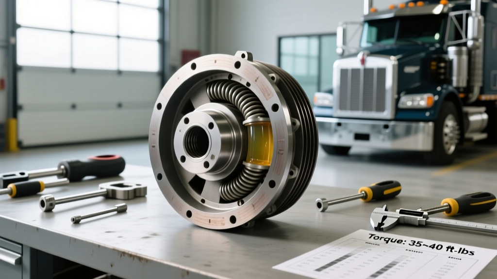
When replacing hydraulic components, adhering to precise torque specifications prevents warped housings, stripped threads in aluminum bellhousings, and fluid leaks.
- Concentric Slave Cylinder to Bellhousing (Typical M6 Bolts): 15 Nm (11 lb-ft). Over-torquing can crack the polymer housing of the CSC.
- External Slave Cylinder to Cast Iron/Aluminum Housing (Typical M8 Bolts): 25 Nm (18 lb-ft).
- Master Cylinder Firewall Nuts (Typical M8 Studs): 12 Nm (9 lb-ft). Use a thread-locking compound if the firewall sheet metal threads are compromised.
- Hydraulic Line Flare Nut (Master to Hard Line): 18 Nm (13 lb-ft). Always use a crowfoot wrench to avoid rounding the soft steel fitting.
Preventive Maintenance Checklist for 2026
To maximize the lifespan of your clutch friction materials and hydraulic hardware, implement this bi-annual inspection routine:
- Fluid Moisture Test: Use a digital brake fluid tester. If moisture content exceeds 2.5%, flush the system immediately with DOT 4 LV or OEM-specified fluid.
- CSC Weep Hole Inspection: Most CSCs feature a small weep hole at the base. A slight film of fluid is normal due to the release bearing's internal grease. However, active dripping indicates a blown internal O-ring, requiring immediate transmission removal and CSC replacement.
- Pedal Return Spring Tension: Verify the pedal returns crisply to the upper stop. A weak return spring can prevent the master cylinder piston from fully retracting, leading to the compensator port blockage issue detailed earlier.
- Clutch Delay Valve (CDV) Evaluation: Many modern manual transmissions feature a CDV in the hydraulic line to smooth out engagement for novice drivers. While not a maintenance item per se, enthusiasts often remove or restrict the CDV to improve shift speed and reduce clutch slip during aggressive driving. If removed, ensure the line is thoroughly bled.
Conclusion
Hydraulic clutch system diagnosis requires a methodical approach that bridges fluid dynamics, mechanical tolerances, and thermal management. By understanding the specific failure modes inherent to high-stress driving environments like the Dairy Ashford corridor, technicians can move beyond reactive repairs and implement robust preventive maintenance protocols. Whether you are measuring pushrod clearance to the thousandth of an inch or executing a meticulous reverse-bleed on a ZF-equipped chassis, precision is the ultimate safeguard for your drivetrain. For further technical reading on hydraulic system standards, refer to the ATE Brake Fluid Specifications Guide to ensure your fluid selection matches your vehicle's exact thermal requirements.