The DIY Misconception: Electrical vs. Hydraulic Schematics
When a manual transmission clutch fails to disengage or feels spongy, internet forums often send novice DIYers down a confusing rabbit hole of electrical troubleshooting. It is surprisingly common to see a weekend mechanic searching for an ac compressor clutch diagram, mistakenly believing that a 12V electromagnetic relay, a wiring fault, or a blown fuse is preventing their clutch from engaging. This fundamental misunderstanding of drivetrain actuation stems from a lack of familiarity with modern manual transmission architecture.
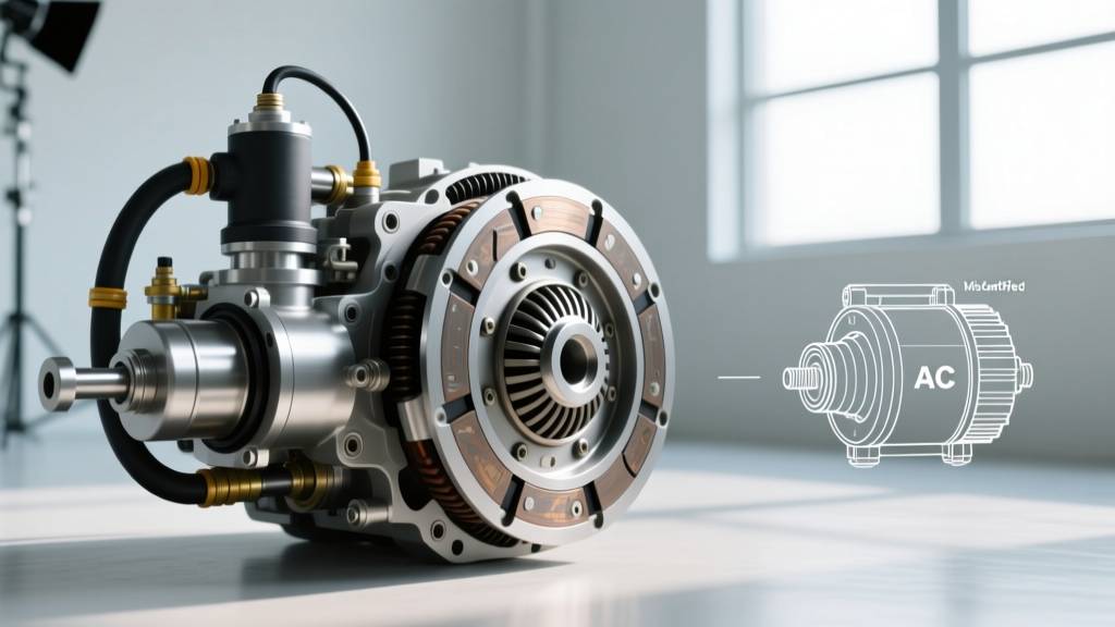
Unlike the electromagnetic PTO (Power Take-Off) clutch on your vehicle's A/C compressor—which relies on a 12V DC circuit, a magnetic coil, and a precise 0.3mm to 0.6mm air gap to engage the pulley—a manual transmission clutch is a purely hydraulic and mechanical system. There are no wiring diagrams, relays, or fuses that will fix a sinking clutch pedal. Proper hydraulic clutch system diagnosis requires an understanding of fluid dynamics, master/slave cylinder bore ratios, and preventive maintenance protocols. As we move through 2026, the integration of automated manual transmissions (AMTs) and advanced hydraulic delay valves has only made this distinction more critical for technicians and advanced DIYers alike.
Core Components of Hydraulic Clutch Actuation
To diagnose a hydraulic clutch issue, you must first isolate the fault to one of the three primary hydraulic components. According to engineering data from Valeo Service, a leading OE manufacturer of clutch actuation systems, the vast majority of warranty claims stem from improper bleeding or fluid contamination rather than catastrophic component failure.
1. The Master Cylinder and Pushrod Clearance
The clutch master cylinder (CMC) converts mechanical pedal force into hydraulic pressure. A common, yet frequently misdiagnosed, issue is internal bypassing. This occurs when the primary EPDM rubber cup passes over the compensation port before the pedal is fully released. The root cause? Incorrect pushrod free play. The pushrod connecting the pedal to the CMC piston must have exactly 0.1mm to 0.5mm of free play. If the pushrod is adjusted too tightly (zero free play), the piston never fully returns to its resting position, blocking the compensation port. This traps fluid, causing the clutch to slip under heavy load as the fluid expands with engine bay heat.
2. Delay Valves and Engagement Shock
Modern manual transmissions, such as the Tremec T56 Magnum and the Ford MT-82, utilize a hydraulic delay valve (or restrictor orifice) in the line between the master and slave cylinder. This valve restricts fluid flow to approximately 0.5 liters per minute during clutch engagement, slowing down the release bearing's movement to prevent driveline shock and gear rattle. If your vehicle exhibits a 'slipping' sensation during rapid upshifts, the delay valve is functioning as designed. However, if the pedal hangs to the floor during high-RPM shifts, the restrictor may be clogged with degraded rubber particulates from a failing master cylinder seal.
3. Concentric Slave Cylinders (CSC) vs. External Slaves
Most 2026 passenger vehicles utilize a Concentric Slave Cylinder (CSC), which mounts directly inside the bellhousing around the transmission input shaft. While space-efficient, CSCs are notorious for heat degradation. The plastic bearing sleeves found on early-generation OE CSCs can melt or warp when subjected to the radiant heat of a slipping clutch disc. When replacing a CSC, always opt for aftermarket units featuring anodized aluminum or high-temp polymer bearing sleeves, and strictly adhere to the OE torque specification for the mounting bolts (typically M6x1.0 bolts torqued to 8-10 Nm).
Diagnostic Matrix: Isolating Hydraulic Failures
Use the following diagnostic matrix to differentiate between hydraulic actuation faults and internal mechanical transmission failures. This prevents unnecessary transmission removal and focuses your preventive maintenance efforts.
| Symptom | Hydraulic Root Cause | Mechanical Root Cause | Diagnostic Test Protocol |
|---|---|---|---|
| Pedal sinks to floor over 30 seconds | Master cylinder internal bypass (EPDM cup failure) | Clutch fork pivot ball wear (external slave only) | Cap master cylinder, pump pedal, watch for fluid level drop in reservoir. |
| Incomplete disengagement (grinding into 1st/Reverse) | Air trapped in CSC or delay valve restriction | Warped pressure plate fingers or seized pilot bearing | Measure slave cylinder stroke with dial indicator (Spec: 12-15mm minimum). |
| Severe chatter on engagement | Fluid contaminated with petroleum (swollen seals) | Oil leak from rear main seal onto friction disc | Inspect fluid color; smell reservoir for hydrocarbons; check for swelling. |
| Pedal vibration at high RPM | Cavitating fluid due to degraded hygroscopic moisture | Worn release bearing or dual-mass flywheel (DMF) failure | Pressure bleed system; if vibration persists, inspect DMF runout (max 1.5mm). |
Preventive Maintenance: Fluid Hygroscopy and Bleeding Protocols
The most neglected aspect of hydraulic clutch system diagnosis is fluid maintenance. Clutch systems share the same fluid type as brake systems, but they operate in a much harsher thermal environment due to their proximity to the engine block and exhaust manifolds.
Understanding DOT 4, DOT 5.1, and the DOT 5 Trap
According to SAE International (Standard J1703) and FMVSS 116, DOT 4 and DOT 5.1 are glycol-ether based and highly hygroscopic. They are designed to absorb ambient moisture into the fluid, preventing localized water pockets from boiling and causing vapor lock. A fresh DOT 4 fluid has a dry boiling point of 230°C (446°F) and a wet boiling point of 155°C (311°F). Over a 3-year interval, the fluid can absorb up to 3% water by volume, drastically lowering the wet boiling point and causing the pedal to feel spongy during aggressive driving.
Critical Warning: Never use DOT 5 (silicone-based) fluid in a hydraulic clutch system. Silicone fluid does not absorb water; instead, water pools at the lowest point of the system (the slave cylinder). When the clutch gets hot, that pooled water boils instantly, resulting in a sudden and total loss of clutch disengagement. Furthermore, silicone fluid will cause the EPDM seals in OE master cylinders to swell and fail.
Proper Pressure Bleeding Specifications
Vacuum bleeding is largely ineffective for modern CSC systems because pulling a vacuum on glycol fluid can cause dissolved gases to come out of suspension, creating false micro-bubbles that mimic a persistent air pocket. The industry standard for 2026 preventive maintenance is pressure bleeding.
- Pressure Setting: Set the motive pressure bleeder to exactly 15-20 PSI. Pressures exceeding 25 PSI can rupture the diaphragm inside the master cylinder reservoir cap or blow out the slave cylinder piston seals.
- Volume Requirement: Push a minimum of 500ml (approx. 16 oz) of fresh DOT 4 or DOT 5.1 fluid through the system to ensure all degraded fluid and microscopic rubber particulates are flushed from the delay valve and slave cylinder.
- Pedal Cycling: Have an assistant slowly depress the clutch pedal to the floor and hold it for 3 seconds while you open the bleeder screw. This forces fluid into the deepest crevices of the CSC bore.
2026 Repair Cost and OEM Part Data
When diagnosis confirms a hydraulic component failure, understanding the current market pricing and part availability is essential. Based on current catalog data from RockAuto and regional labor guides, here is what you can expect for common hydraulic clutch repairs:
- Clutch Master Cylinder Replacement: OE parts (e.g., FTE Automotive or Sachs) range from $45 to $120. Labor is typically 0.8 to 1.2 hours ($120-$200). Total: $165 - $320.
- Concentric Slave Cylinder (CSC) Replacement: Because the CSC is located inside the bellhousing, the transmission must be removed. The part itself costs between $80 and $250. However, labor is extensive, ranging from 4.5 to 7.0 hours depending on the vehicle (e.g., RWD vs. Transverse FWD). Total: $700 - $1,400.
- Hydraulic Line & Delay Valve Delete: For performance applications (like the Ford Mustang MT-82), replacing the plastic OE delay line with a stainless steel braided line and removing the restrictor costs about $60-$90 for parts and 1.0 hour of labor. This significantly improves shift crispness but transfers more shock to the transmission synchronizers.
Final Preventive Takeaway
Stop looking for electrical wiring diagrams when your clutch pedal feels soft. A hydraulic clutch system is a closed-loop fluid circuit governed by Pascal's Law. By adhering to strict 3-year fluid flush intervals, verifying master cylinder pushrod free play, and utilizing proper pressure bleeding techniques, you can extend the life of your CSC and clutch friction materials well past the 100,000-mile mark. Treat the hydraulics with the same respect you give the mechanical friction components, and your manual transmission will reward you with precise, predictable engagement for years to come.