The Anatomy of Hydraulic Clutch Actuation
Hydraulic clutch systems offer self-adjusting precision and reduced mechanical friction compared to traditional cable-actuated setups. Whether you are diagnosing a failing concentric slave cylinder on a C7 Corvette or troubleshooting the hydraulic actuation on an auto clutch bike equipped with a Rekluse RadiusX, the diagnostic principles remain rooted in fluid dynamics, seal integrity, and volumetric displacement. As we navigate the 2026 driving and riding season, the proliferation of high-torque platforms and advanced off-road auto-clutch mechanisms demands a stricter approach to preventive maintenance.
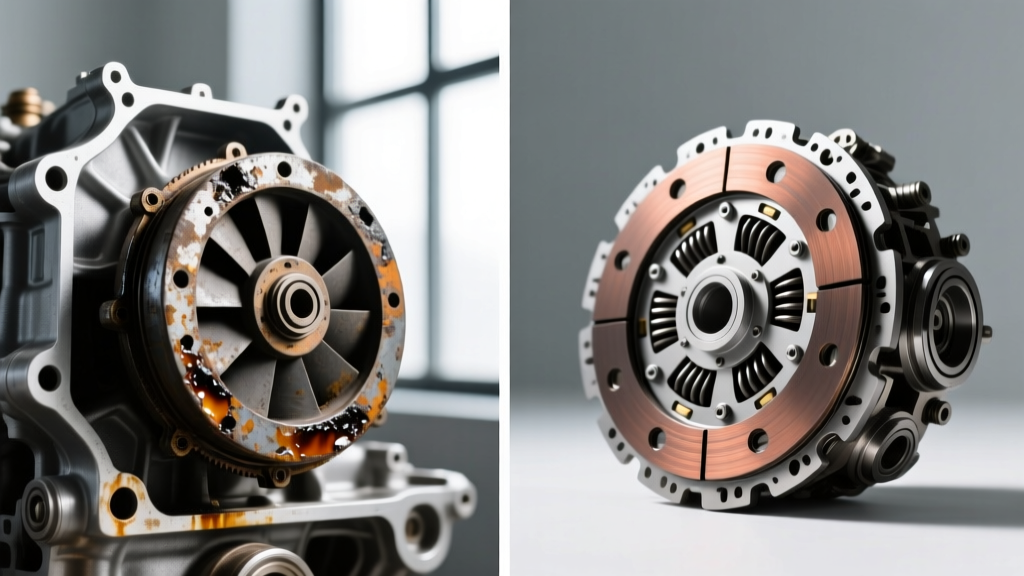
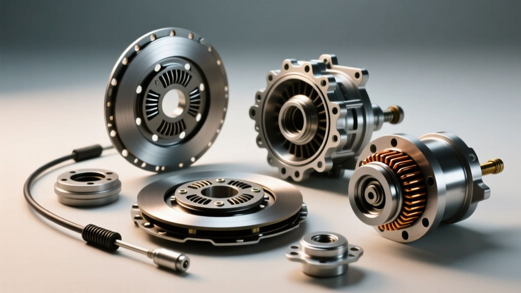
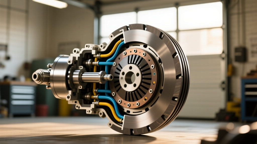
A standard hydraulic clutch circuit consists of a master cylinder, a hard line transitioning into a flexible braided or rubber hose, a slave cylinder (either external lever-actuated or internal concentric), and a pushrod that engages the release bearing. When the lever or pedal is depressed, hydraulic pressure is multiplied and transferred to the slave. Any compromise in this sealed system—from microscopic internal seal bypasses to hygroscopic fluid degradation—will manifest as poor shifting, clutch drag, or complete actuation failure.
Preventive Maintenance: Fluids, Intervals, and Moisture Testing
The most common catalyst for hydraulic clutch failure is neglected fluid. Most automotive and motorcycle clutch systems share their fluid type with the brake system, meaning they rely on DOT-rated glycol-based fluids. These fluids are hygroscopic; they absorb moisture from the atmosphere through microscopic pores in rubber hoses and reservoir seals. Over time, this moisture lowers the fluid's boiling point and promotes internal corrosion on the master cylinder's aluminum bore, leading to seal scoring.
For preventive maintenance, fluid should be flushed every 24 months or 30,000 miles. Use a copper test strip or a digital moisture pen to check fluid health. If moisture content exceeds 2%, immediate flushing is required.
| Fluid Type | Dry Boiling Point (°F) | Wet Boiling Point (°F) | Best Application |
|---|---|---|---|
| DOT 4 (Standard) | 446°F | 311°F | OEM daily drivers, light commuting |
| DOT 4 (High Performance) | 594°F | 420°F | Track cars, heavy-duty towing |
| DOT 5.1 | 518°F | 374°F | Modern European vehicles, ABS-integrated systems |
| Mineral Oil | N/A (Non-Hygroscopic) | N/A | Magura hydraulic systems, specific auto clutch bikes |
Note: Never mix DOT 5 (silicone-based) with DOT 4 or 5.1. Furthermore, systems designed for Mineral Oil (common on certain European motorcycles and aftermarket setups) will suffer catastrophic seal swelling if exposed to glycol-based DOT fluids. Always verify the reservoir cap stamping. For high-performance applications, Motul RBF 600 remains an industry benchmark for its high dry boiling point and consistent lever feel.
Diagnostic Framework: Spotting Master and Slave Cylinder Failure
When a customer or rider reports clutch engagement issues, a systematic diagnostic approach isolates the fault without unnecessary parts swapping.
Symptom 1: The Spongy Lever and Internal Bypass
If the clutch lever or pedal travels to the floor but returns when pumped, you are likely dealing with air in the system or a failing master cylinder cup seal. To differentiate between the two, perform the 'hold-and-observe' test. Depress the lever halfway and hold it with consistent pressure for 60 seconds. If the lever slowly creeps toward the bar/grip while pressure remains constant, the master cylinder's primary cup seal is bypassing fluid internally. The aluminum bore is likely pitted. Replacement of the master cylinder (or a complete rebuild using an OEM seal kit) is mandatory.
Symptom 2: Clutch Drag and Hose Check-Valving
Clutch drag occurs when the clutch does not fully disengage, causing grinding during shifts or creeping at stoplights. While this can indicate a warped friction plate, in hydraulic systems, it is frequently caused by a failing flexible hydraulic hose. As rubber hoses age internally, the inner Teflon or synthetic lining can delaminate, creating a one-way 'check valve' effect. Fluid is forced down to the slave under high pressure, but cannot return to the reservoir when the lever is released. To diagnose this, crack the banjo bolt at the master cylinder. If the lever immediately frees up and the clutch stops dragging, replace the flex hose with a stainless-steel braided line.
Special Focus: Hydraulic Diagnosis on an Auto Clutch Bike
Diagnosing hydraulic actuation takes on a unique urgency when dealing with an auto clutch bike. Systems like the Rekluse Core EXP or RadiusX utilize centrifugal weights (EXP weights) to automatically engage and disengage the clutch based on engine RPM. However, these systems still rely on the OEM hydraulic clutch circuit to provide manual override and baseline disengagement when the bike is at idle or stopped.
On an auto clutch bike, the hydraulic slave cylinder pushrod travel is incredibly sensitive. If the hydraulic system has air, or if the fluid has degraded and expanded, the slave piston may not travel the full 10-12mm required to completely separate the clutch pack at low RPM. The result? The auto-clutch mechanism fails to fully disengage at idle, causing the bike to stall, the rear wheel to chirp, and the EXP weights to suffer premature, catastrophic wear due to continuous friction.
When servicing an auto clutch bike, you must verify the 'free play' at the slave cylinder pushrod. According to Rekluse Technical Support, maintaining exactly 1.0mm to 1.5mm of free play between the slave piston and the actuator arm is critical. Too little free play will cause the clutch to slip at high RPM; too much will prevent the auto-clutch from disengaging at idle, leading to stalling.
Master Cylinder Bore Sizing and Leverage Ratios
Upgrading or replacing hydraulic components requires an understanding of bore sizing. The hydraulic ratio is determined by dividing the slave cylinder bore area by the master cylinder bore area.
- Automotive Applications: A typical passenger car uses a 15.8mm (5/8") master cylinder paired with a 19mm or 22mm concentric slave. This provides a high hydraulic multiplication ratio, necessary to overcome heavy diaphragm spring pressures (often exceeding 2,500 lbs of clamp load).
- Motorcycle & Auto Clutch Bike Applications: Dirt bikes and street fighters typically use 11mm, 12.7mm (1/2"), or 14mm master cylinders. Installing a larger 14mm master cylinder on a bike designed for an 11mm will result in a very firm, abrupt lever feel and reduced pushrod travel at the slave, which can be disastrous for the precise modulation required on an auto clutch bike.
If you are retrofitting a system, aftermarket units like the Brembo 19RCS radial master cylinder offer adjustable leverage ratios, allowing you to fine-tune the hydraulic displacement to match your specific slave cylinder volume.
Step-by-Step Reverse Bleeding and Torque Specifications
Traditional top-down bleeding often leaves air trapped in the high points of the slave cylinder or the hard line routing. For preventive maintenance and absolute system integrity, reverse bleeding (pushing fluid from the slave up to the master) is the professional standard. Using a tool like the Motive Products 0107 Power Bleeder, follow these parameters:
- Preparation: Extract all old fluid from the master reservoir using a turkey baster. Clean the reservoir with isopropyl alcohol to remove glycol sludge.
- Connection: Attach the reverse bleeder to the slave cylinder bleed nipple. Ensure the master cylinder reservoir cap is removed and the diaphragm is taken out to allow fluid to rise.
- Pressurization: Pump the bleeder to 15-20 PSI. Do not exceed 25 PSI, or you risk blowing out the master cylinder reservoir seal.
- Observation: Watch the master reservoir. You will see air bubbles violently purge into the fluid. Once a steady stream of clean, bubble-free fluid enters the reservoir, close the slave bleed nipple.
- Leveling: Extract excess fluid from the master reservoir to bring it to the 'MAX' fill line. Reinstall the diaphragm and cap.
Critical Torque Specs and Hardware
Reusing crushed copper or aluminum washers on banjo bolts is a guaranteed path to micro-leaks and moisture ingress. Always replace crush washers during any hydraulic service.
- Banjo Bolts (M10x1.0 or M12x1.0): 18 - 22 Nm (13 - 16 lb-ft). Always use a backing wrench to prevent twisting the hard line.
- Master Cylinder Clamp Bolts (Motorcycle): 8 - 10 Nm (6 - 7 lb-ft). Overtightening will warp the master cylinder body, causing the piston to bind.
- Slave Cylinder Mounting Bolts: 12 - 15 Nm (9 - 11 lb-ft). Apply medium-strength blue threadlocker (Loctite 243) to prevent vibration-induced backing out.
- Pushrod Locknut (External Slave): 8 Nm (6 lb-ft). Adjust pushrod depth to achieve the manufacturer-specified 1-2mm free play before locking.
Conclusion
Hydraulic clutch systems are marvels of self-adjusting engineering, but they demand rigorous preventive maintenance. By understanding fluid chemistry, monitoring hose integrity, and respecting the precise pushrod travel requirements—especially on specialized platforms like an auto clutch bike—you can eliminate shifting inconsistencies and prevent catastrophic drivetrain wear. Invest in quality reverse-bleeding tools, adhere strictly to torque specifications, and never ignore a lever that feels marginally softer than it did the week before.