The Car Clutch Pedal: Your Primary Diagnostic Interface
In the modern automotive landscape, the manual transmission is a hallmark of driver engagement, yet its actuation system remains a frequent point of diagnostic confusion. Whether you are troubleshooting a classic cable-actuated setup or a modern hydraulic system paired with a dual-mass flywheel (DMF), the car clutch pedal serves as your primary diagnostic interface. As we navigate the 2026 automotive service landscape, manual gearboxes like the Tremec T-56 Magnum F and Honda's rev-matching 6-speeds rely on precise hydraulic and electronic feedback. A comprehensive clutch system inspection checklist is not just about checking fluid levels; it requires a systematic evaluation of mechanical linkages, hydraulic fluid dynamics, and electronic clutch position sensors.
This technical deep-dive provides transmission specialists and advanced DIYers with a rigorous, step-by-step clutch system inspection checklist. We will cover exact measurements, torque specifications, and failure modes associated with Clutch Master Cylinders (CMC), Concentric Slave Cylinders (CSC), and external hydraulic actuators.
Understanding the Hydraulic Actuation Architecture
Over 95% of modern manual vehicles utilize a hydraulic actuation system. When you depress the car clutch pedal, you are mechanically pushing a piston inside the CMC, which displaces incompressible brake fluid through a high-pressure line to the slave cylinder. According to engineering data from ZF Group, modern clutch systems must manage clamping forces exceeding 2,500 lbs while maintaining pedal effort under 35 lbs. This requires flawless hydraulic integrity and precise mechanical geometry.
Phase 1: Mechanical Linkage and Pedal Free-Play
Before cracking open a hydraulic bleeder valve, you must verify the mechanical geometry of the pedal assembly. Incorrect pushrod adjustment is the leading cause of premature clutch wear and incomplete disengagement.
- Pushrod Clearance: There must be a microscopic gap between the CMC piston and the pushrod when the pedal is fully returned. If the pushrod is adjusted too tightly, the CMC cannot fully retract, blocking the compensation port. This traps pressure in the line, causing the clutch to slip under load. Target spec: 0.1mm to 0.5mm of free play at the pushrod.
- Pedal Free-Play Measurement: Measure the distance the pedal travels before resistance is felt. Standard specification for most passenger vehicles (e.g., Subaru WRX, Ford Mustang) is 0.5 to 1.0 inches (12mm to 25mm) at the pedal pad.
- Over-Center Spring Tension: Modern pedals use an over-center assist spring to reduce driver fatigue. If the car clutch pedal snaps back violently or feels notchy at the top of its travel, the spring is fatigued or the pivot bushing is binding. Inspect the nylon pivot bushings for elongation, which can exceed 1.5mm in high-mileage vehicles.
- Pedal Height Verification: Measure from the firewall to the center of the pedal pad. A sagging pedal height indicates a worn firewall (common in older Honda/Acura chassis) or a bent pedal bracket.
Phase 2: Hydraulic System Integrity and Fluid Dynamics
The hydraulic circuit is highly susceptible to moisture contamination and thermal degradation. Most OEMs specify DOT 4 or DOT 5.1 fluid, which are polyglycol-ether based and highly hygroscopic.
Expert Diagnostic Tip: Never rely solely on a gravity bleed for a modern clutch system. The hydraulic lines often feature complex routing and anti-vibration loops that trap micro-bubbles. Always use a pressure bleeder set to 20-30 PSI, and cycle the car clutch pedal slowly through its full stroke 15-20 times to dislodge air pockets trapped in the slave cylinder bore.
Inspecting the Concentric Slave Cylinder (CSC)
Many modern transmissions, including those found in GM LS/LT platforms and European models equipped with Valeo or Sachs clutch kits, utilize a CSC mounted directly inside the bellhousing. Because the CSC rides on the transmission input shaft, a failure requires complete transmission removal.
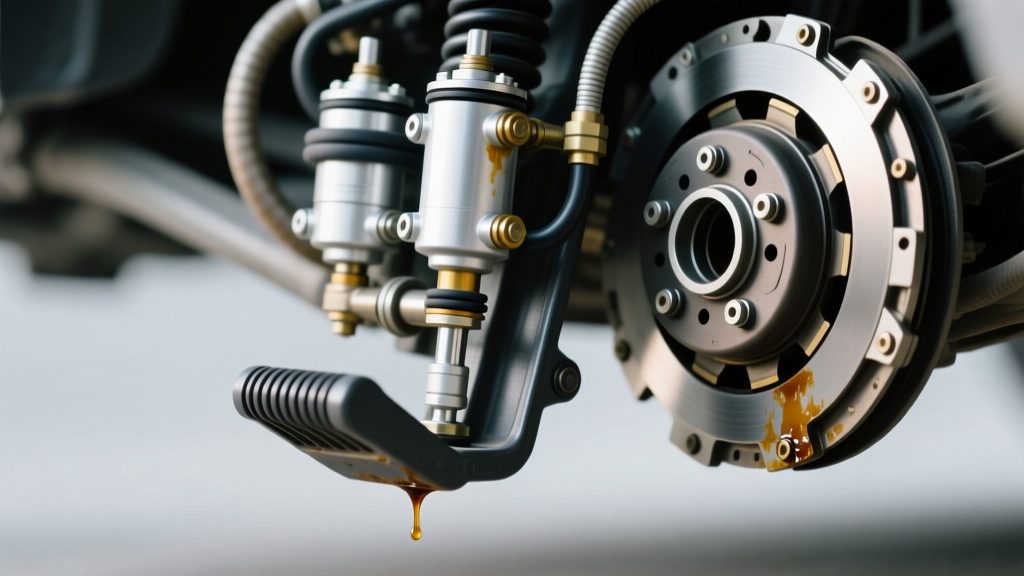
- Visual Inspection: Check the bellhousing inspection cover or weep hole for signs of fluid seepage. DOT fluid will wash away chassis grease and leave a dark, oily residue.
- Release Bearing Play: With the transmission removed, check the CSC bearing for axial play. More than 0.5mm of wobble indicates bearing cage failure, which will cause clutch chatter and severe input shaft wear.
- Plastic vs. Aluminum Lines: Inspect the hydraulic feed line. Many OEMs use plastic lines with quick-connect fittings. These degrade under high under-hood temperatures. Upgrading to braided stainless steel lines with AN-3 fittings is a recommended preventative measure for track-driven vehicles.
Phase 3: Clutch Pedal Diagnostic Matrix
Use the following matrix to correlate specific car clutch pedal feedback with underlying mechanical or hydraulic failures.
| Pedal Symptom | Tactile Feedback | Probable Failure Mode | Diagnostic Action & Spec |
|---|---|---|---|
| Spongy / Mushy | Drops to floor, lacks resistance | Air ingestion or CMC internal seal bypass | Pressure bleed at 30 PSI; rebuild or replace CMC (e.g., Aisin CM-001) |
| Hard to Depress | Notchy, binds at mid-travel | Binding clutch fork pivot ball or failing CSC bearing | Inspect bellhousing; replace fork pivot; apply high-temp moly grease |
| Stays on Floor | No return force after depression | Broken over-center spring or blown CSC internal seal | Replace return spring assembly; check CSC for catastrophic fluid weep |
| Pulsation / Vibration | Rhythmic buzzing through pedal pad | Warped pressure plate diaphragm or damaged DMF | Measure DMF free-play (max 22 degrees); check flywheel runout (max 0.005 in) |
| Slipping Under Load | Pedal feels normal, RPMs flare in 4th/5th gear | Pushrod too tight (blocked compensation port) or oil contamination | Adjust pushrod to 0.5mm gap; inspect rear main seal for leaks |
Phase 4: Electronic Clutch Position Sensors (CPPS)
In 2026, the car clutch pedal is as much an electronic input as a mechanical one. Vehicles equipped with automated rev-matching, cruise control cancellation, and start-stop technology rely on the Clutch Pedal Position (CPP) sensor and the Clutch Start Cancel switch.
Scan Tool PID Analysis
Connect an advanced OBD-II scan tool and monitor the CPP sensor PID while slowly depressing the pedal. The voltage or percentage sweep must be perfectly linear. If you observe a sudden drop from 80% to 20% without a corresponding physical pedal movement, the internal potentiometer track is worn. This will cause erratic rev-matching behavior, potentially leading to over-revving and catastrophic engine valve float when downshifting.
Calibration Requirement: After replacing a CPP sensor or a CMC assembly with an integrated sensor, a clutch pedal position relearn procedure is mandatory. This is typically performed via the scan tool's 'Body Control Module (BCM)' or 'Powertrain Control Module (PCM)' special functions menu.
Final Torque and Assembly Specifications
When your clutch system inspection checklist dictates a replacement of hydraulic or mechanical components, adhering to exact torque specifications is critical to prevent housing cracks and fluid leaks.
- CMC to Firewall Nuts: Typically 10mm or 12mm nuts. Torque to 15-20 Nm (11-15 lb-ft). Do not overtighten, as this will warp the plastic or aluminum master cylinder body, causing internal bypass leaks.
- External Slave Cylinder Bolts: Torque to 18-25 Nm (13-18 lb-ft). Always use a threadlocker (e.g., Loctite 243) on the bolts, as engine vibration frequently backs them out over time.
- Bellhousing to Engine Block: When removing the transmission to access a CSC, ensure you torque the bellhousing bolts to OEM specs upon reassembly. For GM LS/LT engines, this is 50 Nm (37 lb-ft); for Ford Modular/Coyote engines, it ranges from 40-48 Nm (30-35 lb-ft).
- Hydraulic Line Quick-Connects: When reconnecting the hydraulic line to the CMC or CSC, ensure the retaining clip clicks into place. A partially seated quick-connect will hold static pressure but will blow apart under the dynamic 800+ PSI pressure spikes generated during aggressive clutch engagement.
By systematically following this car clutch pedal inspection checklist, technicians can accurately isolate the root cause of actuation failures, avoiding unnecessary transmission removals and ensuring optimal drivetrain longevity.