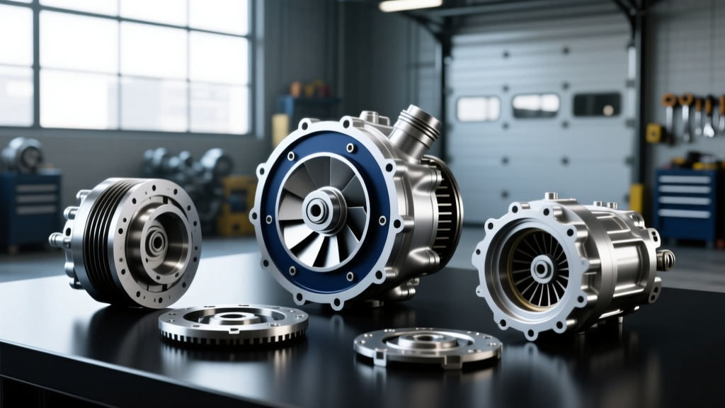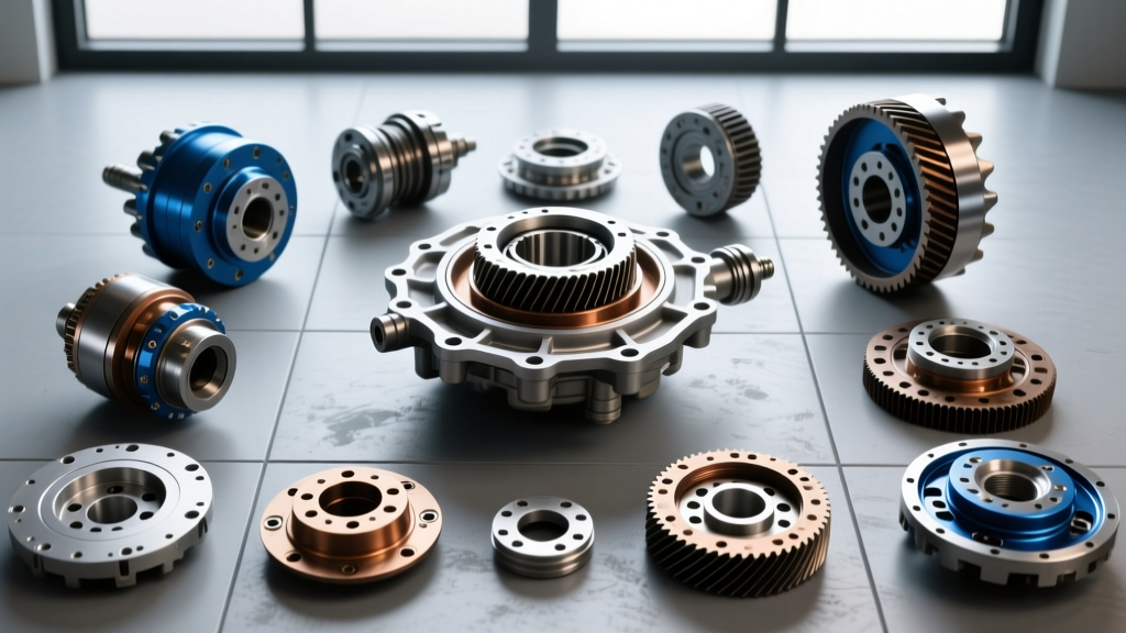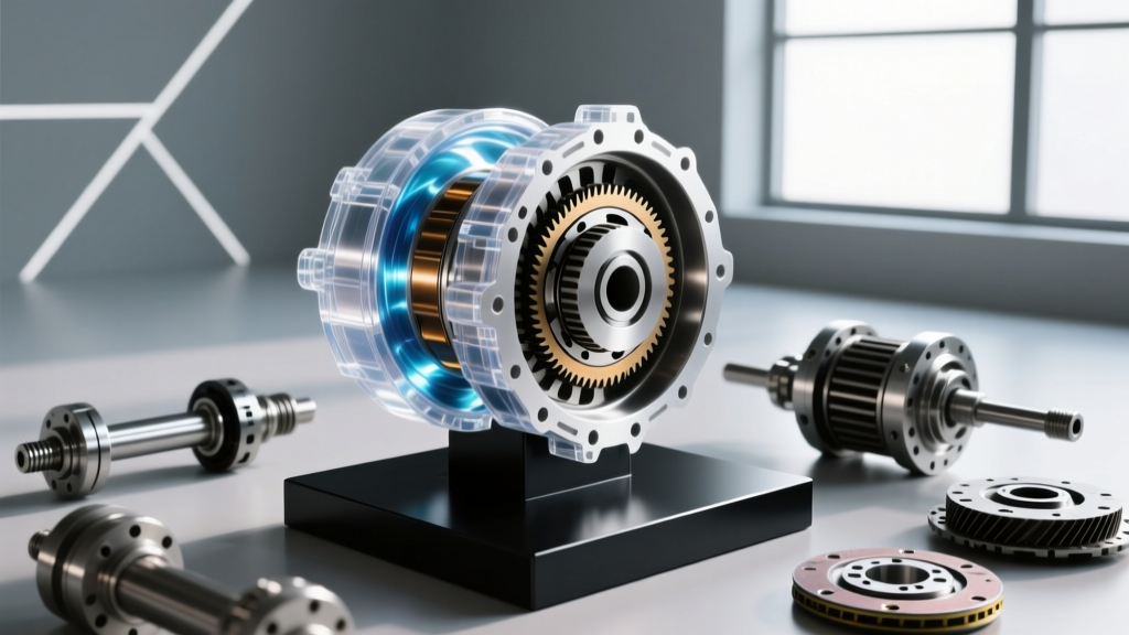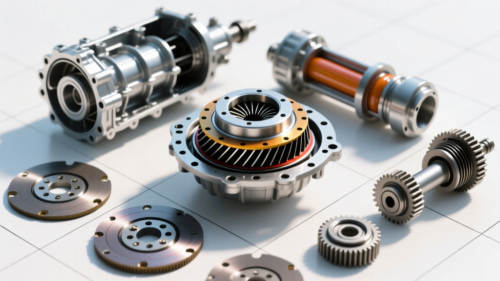
Introduction to the GM 4L60E Torque Converter
The GM 4L60E (Regular Production Option M30) is arguably one of the most ubiquitous automatic transmissions in North American automotive history. Found in millions of Chevrolet, GMC, and Cadillac trucks, SUVs, and performance cars from the early 1990s through the 2010s, its longevity is a testament to robust engineering. However, the transmission itself is only half of the powertransfer equation. The unsung hero sitting between the engine's flexplate and the transmission's input shaft is the torque converter.
For beginners and DIY enthusiasts, the torque converter can seem like a mysterious, sealed metal donut filled with fluid. But understanding how a 4L60E torque converter operates is essential for diagnosing shudder issues, selecting the right stall speed for a cammed engine, or simply performing proper maintenance. In this guide, we will break down the hydrodynamic principles, internal components, and the sophisticated lockup mechanisms that make the 4L60E torque converter a marvel of automotive engineering.
The Hydrodynamic Principle: Two Fans and a Fluid
At its most basic level, a torque converter is a fluid coupling. To visualize how it works, imagine two electric fans placed directly facing each other. If you turn on the first fan (the driver), it blows air across the room. The air hits the blades of the second, unplugged fan (the driven), causing it to spin.
In a 4L60E torque converter, automatic transmission fluid (ATF) replaces the air, and the fans are replaced by precisely engineered centrifugal pumps and turbines. The engine drives the first 'fan,' which accelerates the fluid outward. This high-velocity fluid strikes the second 'fan,' transferring kinetic energy and turning the transmission's input shaft. Because there is no direct mechanical connection during this phase, the engine can idle while the vehicle remains stationary, acting as an automatic, fluid-based clutch.
Inside the Shell: Core Components
To truly grasp the 4L60E torque converter's operation, you must understand its four primary internal components. Each plays a distinct role in managing power delivery and efficiency.
1. The Impeller (Pump)
The impeller is welded directly to the outer shell of the torque converter. The converter shell is bolted to the engine's flexplate, meaning the impeller always spins at exact engine RPM. As it rotates, centrifugal force pushes ATF outward and forward into the turbine. The impeller's curved vanes are designed to maximize fluid velocity and directional flow.
2. The Turbine
Sitting directly opposite the impeller, the turbine is connected to the transmission's input shaft via a splined hub. When the high-velocity fluid from the impeller strikes the turbine's vanes, it causes the turbine to spin, thereby driving the transmission. After passing through the turbine, the fluid exits at the center, carrying residual kinetic energy that must be managed.
3. The Stator (The Multiplier)
Positioned between the impeller and the turbine on a one-way clutch (sprag), the stator is the secret to torque multiplication. When fluid exits the turbine, it is traveling in a direction that would oppose the impeller's rotation if left unchecked. The stator's angled blades catch this returning fluid and redirect it back into the impeller in the direction of rotation. This 'recycling' of fluid energy is what allows the converter to multiply engine torque during initial acceleration.
4. The Torque Converter Clutch (TCC)
Located at the front of the turbine assembly, the TCC is a friction-lined piston. When engaged, it mechanically locks the turbine to the converter shell (and thus the engine), eliminating fluid slippage and creating a 1:1 direct mechanical connection for optimal highway fuel efficiency.
Torque Multiplication vs. The Coupling Phase
A common misconception is that a torque converter always multiplies power. In reality, it operates in two distinct phases based on the speed differential (slip) between the impeller and the turbine.
- Stall and Multiplication Phase: When you brake-torque a 4L60E or launch from a stoplight, the impeller is spinning much faster than the turbine. The stator remains locked by its one-way clutch, redirecting fluid and multiplying engine torque by a factor of roughly 1.8:1 to 2.2:1. This is why a 300 lb-ft engine can apply over 500 lb-ft of twisting force to the transmission input shaft during a hard launch.
- Coupling Phase: As the vehicle accelerates and the turbine speed catches up to roughly 90% of the impeller speed, the fluid returning from the turbine changes its angle of attack. It now strikes the back side of the stator blades, causing the one-way clutch to release. The stator freewheels, and the converter acts as a simple fluid coupling, no longer multiplying torque but merely transferring it with minimal slippage.
4L60E TCC Lockup and PWM Technology
The 4L60E introduced significant electronic advancements over its hydraulic predecessor, the 700R4. One of the most critical is the Pulse Width Modulated (PWM) Torque Converter Clutch solenoid. Early transmissions applied the TCC like a harsh on/off light switch, causing a noticeable 'clunk' or jolt when locking up at highway speeds.
The 4L60E utilizes a PWM solenoid to modulate hydraulic pressure to the TCC apply valve. By rapidly pulsing the solenoid (often at frequencies around 300 Hz), the Powertrain Control Module (PCM) can precisely control the apply rate. This allows for 'Electronic Controlled Capacity Clutch' (ECCC) operation, where the TCC is permitted to slip by 20 to 50 RPM even while 'locked.' This micro-slipping absorbs engine harmonics and torsional vibrations, drastically reducing NVH (Noise, Vibration, and Harshness) and preventing driveline shudder.
Expert Insight: TCC shudder in a 4L60E is rarely a mechanical failure of the clutch friction material itself. It is most frequently caused by wear in the TCC apply valve bore inside the valve body, leading to cross-leaking of PWM fluid. Upgrading to a Sonnax TCC PWM valve kit is the industry-standard fix for high-mileage shudder.
Stall Speed: Flash vs. Brake
When upgrading a 4L60E for a modified engine, understanding stall speed is critical. Stock 4L60E converters typically feature a stall speed between 1,600 and 1,800 RPM.
- Brake Stall: The maximum RPM the engine can reach while holding the brakes firmly applied and the throttle wide open. This is limited by engine torque output and brake holding capacity.
- Flash Stall: The actual RPM at which the converter 'catches' and begins to accelerate the vehicle during a full-throttle launch from a dead stop. This is the true operational stall speed and is heavily dependent on the engine's torque curve and the vehicle's weight-to-gearing ratio.
4L60E Torque Converter Specifications & Data
| Parameter | Stock GM 4L60E (OEM) | Performance Upgrade (e.g., Circle D 245mm) |
|---|---|---|
| Diameter | 298mm (11.7 inches) | 245mm (9.6 inches) |
| Stall Speed (Flash) | 1,600 - 1,800 RPM | 3,200 - 3,600 RPM |
| Torque Multiplication Ratio | ~1.95:1 | ~2.40:1 |
| TCC Friction Material | Standard Woven Carbon | Kevlar / High-Carbon Billet |
| Approximate Fluid Capacity | 5.0 Quarts (Converter Only) | 3.5 Quarts (Converter Only) |
| Billet Components | None (Stamped Steel) | Billet Cover, Billet Stator, Billet Hub |
Maintenance: Fluids, Flushing, and Torque Specs
Proper maintenance of the 4L60E torque converter requires adherence to specific fluid types and assembly procedures. The original Dexron III specification has been superseded by ACDelco Dexron VI, which offers superior shear stability and oxidation resistance. The total system capacity, including the transmission pan, cooler lines, and torque converter, is approximately 11.2 to 12 quarts.
When reinstalling a 4L60E torque converter, it must be fully seated into the transmission oil pump. You must feel three distinct 'drops' or clicks as the converter hub passes through the turbine splines, the stator support, and finally seats into the oil pump drive gear. Failure to fully seat the converter will result in immediate oil pump destruction upon engine start.
Furthermore, the flexplate-to-converter bolts are critical. For standard 3/8'-16 UNF Grade 8 bolts, the factory torque specification is 35 lb-ft. Always apply a medium-strength threadlocker (such as Loctite 243) to prevent these bolts from backing out, which can lead to catastrophic flexplate cracking. For deeper technical diagnostics regarding valve body wear and TCC hydraulic circuits, resources from the Sonnax Technical Resources database and the Automatic Transmission Rebuilders Association (ATRA) remain the gold standards for transmission specialists in 2026.