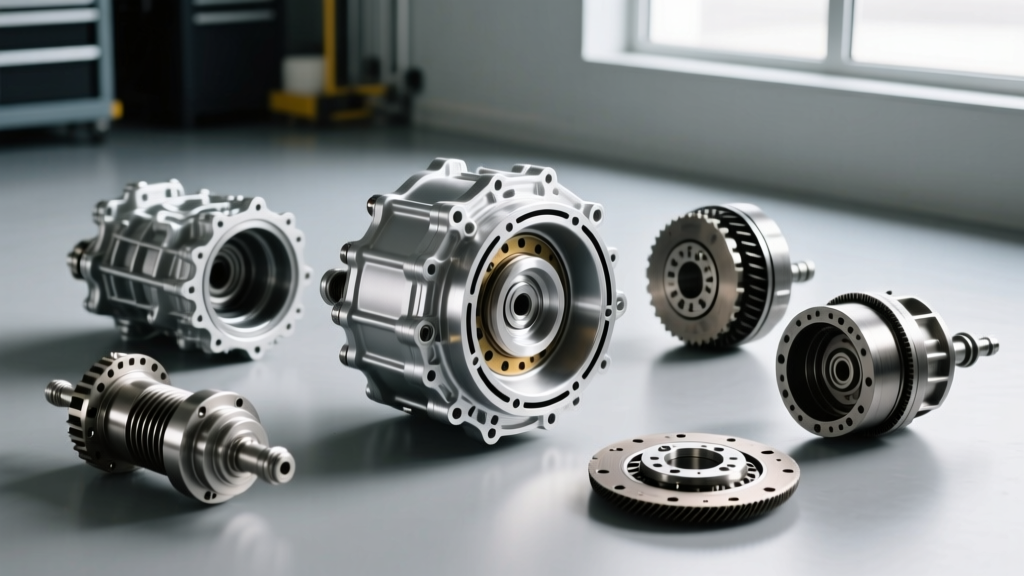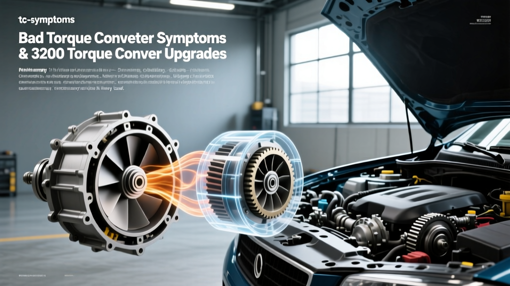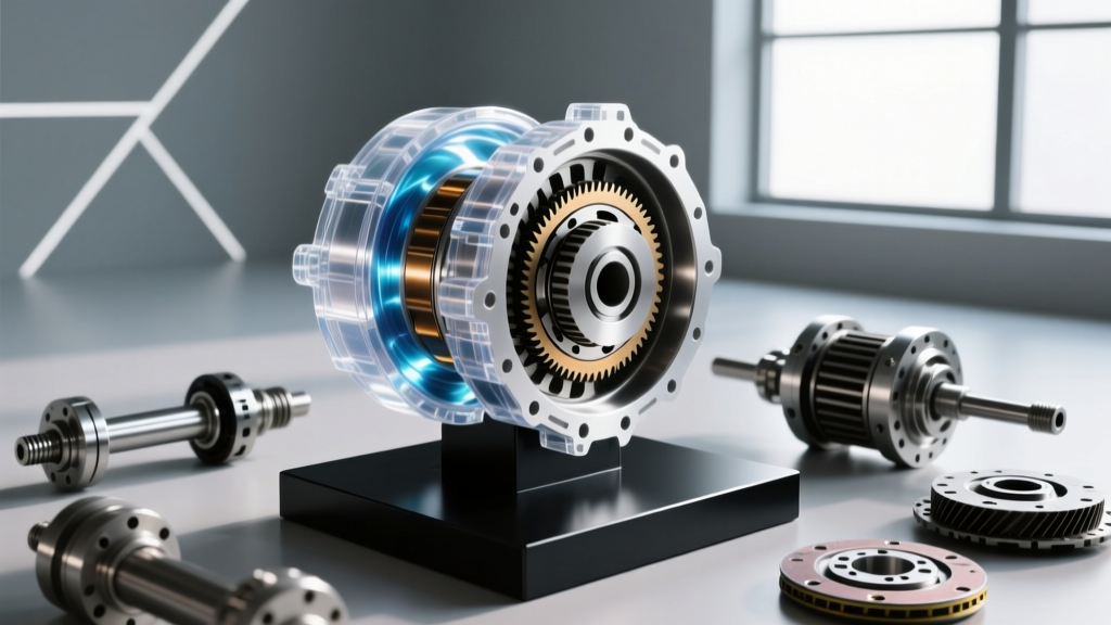
When you press the accelerator on an automatic vehicle, the engine revs, and the car surges forward. But unlike a manual transmission that relies on a mechanical friction disc to connect the engine to the gearbox, an automatic utilizes a hydrodynamic marvel. This component, often referred to in global automotive engineering as a torque converter gearbox interface, is the unsung hero of modern drivetrains. Whether you are driving a classic muscle car with a GM 4L60E or a modern luxury sedan equipped with a ZF 8HP, understanding how this fluid coupling operates is essential for diagnosing drivability issues and maintaining transmission health.
The Anatomy of a Torque Converter Gearbox System
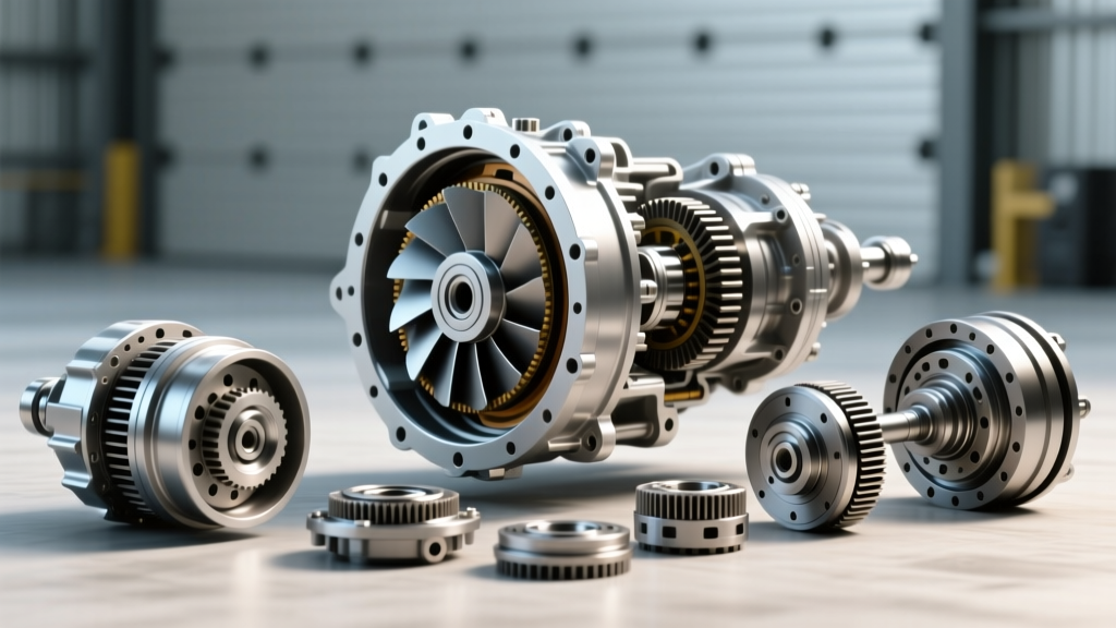
To understand the operation, we must look inside the welded steel housing. A torque converter is essentially a centrifugal pump mated to a hydraulic turbine, filled with Automatic Transmission Fluid (ATF). It consists of four primary components:
- The Impeller (Pump): Bolted directly to the engine's flexplate, the impeller spins at engine RPM. Its curved vanes draw ATF from the center and fling it outward using centrifugal force.
- The Turbine: Connected to the transmission's input shaft, the turbine sits facing the impeller. As ATF is thrown outward by the impeller, it strikes the turbine's vanes, transferring rotational energy and turning the input shaft.
- The Stator: Nestled between the impeller and turbine, the stator is mounted on a one-way clutch (sprag). Its job is to redirect the returning ATF back into the impeller, aligning with the impeller's rotation to multiply torque.
- The Torque Converter Clutch (TCC): A friction-lined piston that mechanically locks the turbine to the impeller housing at cruising speeds, eliminating parasitic fluid slippage.
The Three Stages of Hydrodynamic Operation
A torque converter gearbox does not operate in a single static state; it transitions through three distinct hydraulic phases based on vehicle speed and engine load.
1. The Stall Phase
Imagine you are at a red light. Your foot is on the brake, but the engine is idling. The impeller is spinning, but the turbine is held stationary by the brakes. The ATF churns violently, creating heat but transferring minimal torque. The maximum RPM the engine can reach under these conditions with the brakes fully applied is known as the 'stall speed.' For a stock GM 4L60E, this is typically around 1,500 to 1,800 RPM. High-performance aftermarket converters can push this to 3,500 RPM or higher to keep the engine in its peak powerband during launch.
2. The Acceleration (Torque Multiplication) Phase
When the light turns green and you release the brake, the turbine begins to spin. Because the turbine is moving slower than the impeller, the ATF returns to the impeller at an angle that would normally oppose rotation. Here, the stator's one-way clutch locks up. The stator vanes redirect the fluid to flow with the impeller, effectively adding the fluid's kinetic energy to the engine's mechanical energy. This hydraulic leverage allows a torque converter gearbox to multiply engine torque by a ratio of up to 2.5:1, providing the aggressive off-the-line acceleration characteristic of automatics.
3. The Coupling Phase
As the vehicle reaches roughly 40-50 MPH, the turbine speed catches up to about 90% of the impeller speed. The returning ATF changes its angle of attack, causing the stator's one-way clutch to overrun (freewheel). The stator spins freely, and the converter acts as a simple fluid coupling. At this stage, torque multiplication ceases, and the ratio is effectively 1:1.
Comparing Modern Torque Converter Gearbox Configurations
Not all converters are tuned identically. Engineering teams calibrate stall speeds, lockup strategies, and fluid capacities based on the vehicle's intended use. Below is a comparison of three ubiquitous automatic transmissions and their torque converter specifications.
| Transmission Model | Stock Stall Speed | TCC Lockup Strategy | Fluid Capacity (Pan Drop) |
|---|---|---|---|
| GM 4L60E (V8 Applications) | 1,500 - 1,800 RPM | 3rd/4th Gear (On/Off PWM) | 5.0 - 6.0 Quarts (Dexron VI) |
| ZF 8HP70 (Chrysler/BMW) | 1,800 - 2,100 RPM | 2nd Gear Onward (Slip-Controlled) | 4.0 - 5.5 Quarts (ZF Lifeguard 8) |
| Ford 10R80 (Mustang/F-150) | 1,600 - 1,900 RPM | 1st Gear Onward (Multi-Plate TCC) | 10.0 - 11.0 Quarts (Mercon ULV) |
As highlighted by transmission engineering resources at Sonnax, modern ZF and Ford units utilize advanced slip-controlled lockup clutches. Instead of a harsh mechanical engagement, the Transmission Control Module (TCM) uses Pulse Width Modulation (PWM) to intentionally slip the TCC by 20-40 RPM. This micro-slipping dampens engine harmonics and NVH (Noise, Vibration, and Harshness), allowing the lockup clutch to engage as early as 2nd gear or even 1st gear in the 10R80, vastly improving fuel economy.
The Torque Converter Clutch (TCC) and Shudder Symptoms
While the hydrodynamic coupling is brilliant for low-speed maneuverability, fluid slippage generates immense heat and robs fuel efficiency at highway speeds. The TCC solves this by physically locking the turbine to the converter cover. When the TCM commands lockup, hydraulic pressure forces a friction-lined piston against the machined inner surface of the converter housing.
However, this friction material is highly susceptible to degradation. If the ATF loses its specialized friction modifiers (often due to extended drain intervals or overheating), the TCC cannot maintain its micro-slip. Instead of a smooth 30 RPM slip, the clutch will aggressively grab and release hundreds of times per second. This manifests as TCC shudder—a rhythmic vibration felt through the chassis, typically occurring between 35 and 55 MPH under light throttle application. Beginners often mistake this for a misfiring engine or a warped brake rotor, but it is a hallmark symptom of torque converter friction failure.
Installation Specifications and Best Practices
For the DIY mechanic or apprentice technician replacing a torque converter gearbox assembly, precision is non-negotiable. Improper installation will destroy the transmission oil pump within the first ten miles.
- Seating the Converter: You must feel three distinct 'clunks' or drops when sliding the converter onto the transmission input shaft. These correspond to the turbine splines, the stator support shaft, and the oil pump drive gear. If the converter is not fully seated, the flexplate will crush the converter against the pump, causing catastrophic failure.
- Endplay Measurement: Using a dial indicator on the torque converter pads, measure the distance to the flexplate. Ideal clearance is typically between 0.060" and 0.125". If the gap is too tight, the converter will bottom out and bind. If too wide, the flexplate will warp when bolted down.
- Torque Specs: When mating the converter to the flexplate, always use new Grade 8 or OEM bolts with a medium-strength threadlocker (e.g., Loctite 243). For a standard GM LS flexplate, torque the converter bolts to 46 lb-ft in a star pattern. The bellhousing-to-engine block bolts should be torqued to 37 lb-ft (for M10 bolts) to ensure perfect alignment.
Diagnosing Internal Converter Failures
If you suspect internal failure within the torque converter gearbox system, visual inspection of the ATF is your first clue. Drop the transmission pan and inspect the fluid. A fine, silver glitter is normal wear from the clutch steels and thrust washers. However, if you find chunky metallic debris, brass-colored flakes (indicative of stator needle bearing failure), or black, burnt-smelling fluid with heavy carbon deposits, the internal one-way clutch or thrust bearings have likely disintegrated.
According to diagnostic guidelines outlined by HowStuffWorks Automotive, a failing stator sprag will result in a severe loss of low-end acceleration, as the stator freewheels in both directions, eliminating torque multiplication. Conversely, if the stator locks up in both directions, the vehicle will struggle to reach highway speeds and the transmission will overheat rapidly due to extreme fluid turbulence.
Final Thoughts on Hydrodynamic Drivetrains
The torque converter gearbox interface remains a masterpiece of fluid dynamics. By seamlessly multiplying torque during acceleration and mechanically locking up for highway efficiency, it bridges the gap between the internal combustion engine and the planetary gearsets. Understanding the delicate balance of the impeller, turbine, and stator not only demystifies automatic transmission operation but also equips you with the knowledge to accurately diagnose shudder, slipping, and overheating symptoms before they result in a stranded vehicle.