Decoding the Transmission Oil Cooler Diagram for Extreme Heat
As we navigate the automotive landscape in 2026, the proliferation of complex 8-speed and 10-speed automatic transmissions—such as the Ford 10R80, GM 10L90, and ZF 8HP70—has introduced unprecedented thermal management challenges. These units rely on aggressive torque converter lockup strategies and intricate internal lube circuits that generate immense friction heat. When operating in extreme environments like the deserts of Nevada or the humid, high-ambient-temperature corridors of the Gulf Coast, factory cooling systems are routinely overwhelmed. To combat this, enthusiasts and fleet managers must look beyond OEM specifications and design a custom hot-climate transmission oil cooler diagram that prioritizes maximum BTU rejection without sacrificing lube circuit pressure.
Understanding how to read, modify, and optimize a transmission oil cooler diagram is the difference between a transmission that survives 150,000 miles in harsh conditions and one that bakes its fluid into varnish by 60,000 miles. This guide provides expert-level routing configurations, component sizing, and precision installation specifications for severe-duty applications.
The Thermal Breaking Point of Modern ATF
Before altering your cooling circuit, you must understand the thermal limits of Automatic Transmission Fluid (ATF). According to Amsoil's research on automatic transmission fluid temperature degradation, the ideal operating temperature for most synthetic ATFs is between 175°F and 195°F. Once fluid temperatures cross the 220°F threshold, oxidation accelerates exponentially. For every 20°F increase above 200°F, the operational lifespan of the fluid is effectively cut in half. At 250°F, internal clutch materials begin to glaze, and Viton or nitrile O-rings harden and crack, leading to catastrophic pressure drops and slip-induced failure.
OEM vs. Auxiliary: Where Factory Diagrams Fall Short
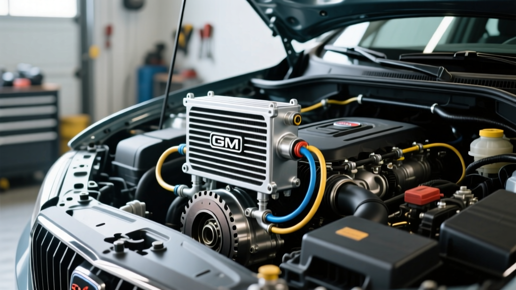
A standard factory transmission oil cooler diagram typically routes hot fluid from the transmission output port directly into the radiator's in-tank cooler. From there, it flows to a small, front-mounted auxiliary cooler before returning to the transmission. In moderate climates, the radiator in-tank acts as both a cooler (when the engine is at operating temp) and a heater (during cold starts).
However, in 110°F+ ambient heat, the radiator's coolant can easily exceed 215°F. At this point, the in-tank cooler ceases to reject heat and instead adds thermal load to the ATF. Furthermore, as detailed in Sonnax's technical guide on cooler flow and lube regulation, restrictive OEM cooler circuits can trigger the transmission's internal thermal bypass valves. When these valves open to protect the cooler from over-pressurization, uncooled oil is sent directly back to the lube circuits, defeating the purpose of the cooling system entirely.
The 3 Optimal Hot-Climate Routing Configurations
When drafting your upgraded transmission oil cooler diagram, you must choose a routing strategy that matches your specific vehicle and use case. Below are the three primary configurations utilized by transmission builders for severe heat.
| Configuration | Routing Path | Best Application | Pros & Cons |
|---|---|---|---|
| Series Stack (OEM + Aux) | Trans -> Radiator -> Aux Cooler -> Trans | Light towing in 100°F+ climates | Easy install; relies on radiator temp which can be a bottleneck in extreme heat. |
| Radiator Bypass (Dedicated) | Trans -> High-Capacity Aux Cooler -> Trans | Desert racing, heavy sled pulling | Maximum BTU rejection; requires external thermostat to prevent overcooling in winter. |
| Thermostatic Parallel | Trans -> Bypass Valve -> (Radiator OR Aux) -> Trans | Year-round daily driving & towing | Optimal temp control; complex plumbing and higher cost ($250+ for valves). |
Configuration 1: The Radiator Bypass (Desert Towing Setup)
For trucks operating consistently in ambient temperatures above 105°F (e.g., Arizona summers), bypassing the radiator in-tank cooler is mandatory. By routing the transmission output directly to a massive front-mounted stacked-plate cooler, you eliminate the radiator's thermal transfer bottleneck. To execute this diagram, you will need a high-flow cooler rated for at least 30,000 GVW, such as the Hayden 678 Rapid-Cool (approx. $75) or the Derale 13504 Series 8000 (approx. $85).
Configuration 2: The Thermostatic Bypass (The Ultimate 2026 Solution)
If your vehicle sees sub-freezing winters but also tows heavy loads in the summer, a static bypass will cause the transmission to run too cold, preventing the ATF from reaching optimal viscosity and causing torque converter shudder. Integrating a thermostatic bypass valve (like the Derale 13011 Fluid Control, ~$140) into your transmission oil cooler diagram allows the fluid to circulate through a closed loop until it hits 180°F, at which point the wax-element valve opens and routes flow to the massive auxiliary cooler.
Sizing the Cooler: BTU Rejection and CFM Requirements
A common mistake when modifying a transmission oil cooler diagram is selecting a cooler based solely on physical dimensions rather than thermal dynamics and pressure drop. Modern transmissions like the GM 6L80 and 8L90 require high cooler flow volumes (often exceeding 1.5 Gallons Per Minute at highway speeds) to maintain adequate lube pressure to the planetary gearsets.
- Tube-and-Fin: High airflow efficiency, but prone to high pressure drop. Not recommended for 10-speed transmissions with complex lube requirements.
- Plate-and-Fin: Good compromise of BTU rejection and flow. Ideal for lighter vehicles or secondary cooling.
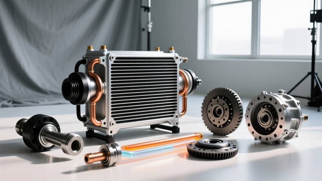
- Stacked-Plate: The gold standard for hot climates. Offers the highest BTU/hr rejection with the lowest pressure drop (often under 3 PSI). Models like the Mishimoto MMTC-U ($160) utilize this design to handle the sheer fluid volume of modern 10L90 transmissions.
Expert Tip: If your cooler is mounted behind a dense radiator or intercooler stack, you must supplement passive airflow with an active pusher/puller fan. Aim for a fan rated at a minimum of 1,200 CFM (Cubic Feet per Minute) wired to a thermal switch set at 190°F.
Precision Installation: Fittings, Hoses, and Torque Specs
A flawless transmission oil cooler diagram is useless if the plumbing restricts flow or leaks under pressure. Upgrading from factory rubber slip-fit hoses to braided stainless steel lines and AN-fittings is highly recommended for hot-climate durability.
Line Sizing and Flow Restrictions
Never use 5/16-inch internal diameter (ID) hose for a heavy-duty auxiliary cooler setup. The restriction will starve the lube circuit. Always use a minimum of 3/8-inch ID hose or AN-8 braided lines. If your transmission case features 5/16-inch barbed fittings (common on older GM 4L60E units), use a stepped brass adapter to transition to 3/8-inch hose immediately outside the case.
Avoiding the 6L80 and ZF 8HP Quick-Disconnect Traps
Modern transmissions utilize plastic quick-disconnect fittings at the case to speed up assembly line production. In extreme heat, these plastic collars become brittle and snap upon removal.
- GM 6L80 / 8L90: Use a dedicated 5/16-inch quick-disconnect removal tool (Lisle 39960). When installing aftermarket billet aluminum AN-adapters into the aluminum transmission case, apply Loctite 565 (PTFE Thread Sealant) and torque to exactly 12-15 lb-ft. Over-torquing will crack the cast aluminum case, resulting in a $4,000 replacement.
- ZF 8HP (Chrysler/BMW/Ford): The ZF 8HP uses specific plastic retainer clips on the cooler lines. Do not attempt to thread AN-fittings into the mechatronic sleeve area. Instead, retain the factory quick-disconnects at the transmission, and splice into the lines using high-pressure inline unions, securing them with constant-tension T-bolt clamps torqued to 45 in-lb.
Proactive Maintenance for Hot Climate Setups
Even with a perfectly executed transmission oil cooler diagram, extreme heat accelerates the depletion of ATF friction modifiers and anti-wear additives. In severe-duty hot climates, abandon the manufacturer's "lifetime fluid" claims. Perform a drain-and-fill (not a high-pressure flush, which can dislodge debris into the valve body) every 30,000 miles. Use a high-quality synthetic fluid with an elevated Noack Volatility rating and a high flash point, such as Amsoil Signature Series or Red Line D4, to ensure your transmission survives the harshest environments on the road.