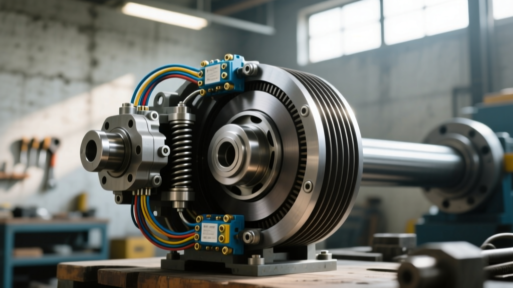
The Intersection of PTO Systems and Main Clutch Diagnostics
In the realm of heavy-duty and commercial vehicles, diagnosing drivetrain vibrations and engagement faults requires looking beyond the main friction clutch. For Class 8 trucks like the Freightliner Cascadia, Peterbilt 579, and Kenworth T680, auxiliary systems are inextricably linked to the primary driveline. When operators report severe clutch chatter, intermittent disengagement, or harmonic vibrations under load, technicians often prematurely condemn the main transmission clutch. However, in vehicles equipped with auxiliary hydraulic or mechanical drives, the root cause frequently traces back to a failing electromagnetic or hydraulic Power Take-Off (PTO) unit. Specifically, a misinterpreted pto clutch wiring diagram or a degraded electrical circuit can cause partial PTO clutch engagement, creating massive parasitic drag and harmonic feedback that perfectly mimics a failing main clutch.
As we navigate the 2026 landscape of commercial fleet maintenance, understanding the electrical architecture of PTO systems is no longer optional—it is a critical diagnostic competency. This guide explores the intricacies of heavy-duty PTO clutch wiring, identifies how electrical faults manifest as mechanical clutch symptoms, and outlines performance upgrades for high-torque commercial applications.
Decoding the Heavy-Duty PTO Clutch Wiring Diagram
Modern heavy-duty PTOs, such as the Parker Chelsea 240 Series or the Muncie M66, rely on complex electrical solenoids or electromagnetic clutches to engage the countershaft gears. Unlike legacy mechanical linkages, these systems utilize 12V or 24V DC circuits governed by the vehicle’s Body Control Module (BCM) or a dedicated PTO controller.
A standard heavy-duty pto clutch wiring diagram consists of several critical nodes:
- Primary Power Feed: Typically a 10 AWG or 8 AWG wire routed directly from the battery bank through a 30A or 40A ATC/ATO fuse block.
- Control Circuit (Signal): A 16 AWG wire originating from the dashboard PTO switch, passing through safety interlocks (parking brake, neutral safety switch, and clutch pedal position sensor).
- Relay Logic: Heavy-duty electromagnetic clutches draw significant inrush current (often 8 to 12 amps at 24V). The wiring diagram will always feature a heavy-duty ISO relay to prevent the dashboard switch from melting.
- Ground Paths: Dedicated chassis grounds. Relying on the transmission casing for a ground path is a common installation error that leads to severe voltage drops.
Expert Insight: When tracing a PTO wiring schematic, always verify the ECU interlock pins. In modern multiplexed systems, the PTO will not receive a ground signal from the relay unless the BCM confirms the transmission is in neutral and the parking brake is set via the J1939 CAN bus network.
How PTO Wiring Faults Mimic Main Clutch Failure
Why do technicians confuse PTO electrical faults with main clutch mechanical failure? The answer lies in parasitic harmonic vibration. When the wiring diagram reveals a circuit with high resistance—perhaps due to corroded relay terminals or an undersized ground wire—the electromagnetic PTO clutch receives insufficient voltage. Instead of fully snapping into engagement, the clutch armature "hovers" or slips against the rotor.
This slipping generates intense localized heat and severe torsional vibration that travels directly through the transmission input shaft. The driver experiences this as violent clutch chatter when attempting to move the vehicle from a standstill, or a rhythmic shudder in the driveline. Before dropping an Eaton Fuller Endurant transmission to replace a $1,500 main clutch assembly, savvy fleet technicians pull the pto clutch wiring diagram to rule out auxiliary slip.
Key Symptoms of PTO Electrical Slip
- Chatter at Idle: Vibration present even when the main clutch is fully depressed, indicating the PTO clutch is dragging due to residual magnetism or partial voltage engagement.
- Whining Under Load: A high-pitched frequency noise originating from the transmission side cover, signaling the PTO gear is bouncing against the countershaft due to weak solenoid holding force.
- Intermittent Disengagement: The auxiliary equipment (e.g., dump bed hoist or snowplow hydraulics) stalls randomly, caused by thermal overload in the PTO clutch coil due to voltage drop.
Performance Upgrades: High-Torque PTO Clutch Kits
For commercial fleets operating in severe-duty cycles—such as heavy hauling, continuous mixer operations, or extreme cold-weather snow removal—standard PTO clutches often suffer from premature coil burnout and armature wear. Upgrading to a high-torque electromagnetic clutch assembly is a proven performance enhancement. Brands like Warner Electric and Ogura offer heavy-duty industrial clutches designed to withstand the brutal shock loads of Class 8 drivetrains.
Below is a comparison between standard OEM replacements and performance-grade upgrades:
| Specification | Standard OEM PTO Clutch | Performance Upgrade (e.g., Warner 540 Series) |
|---|---|---|
| Torque Capacity | 250 - 400 lb-ft | 800 - 1,200 lb-ft |
| Operating Voltage | 12V / 24V DC | 24V DC (Optimized for low-amp draw) |
| Coil Resistance | 3.5 - 5.0 Ohms | 7.0 - 9.0 Ohms (Reduces heat generation) |
| Armature Air Gap | 0.015" - 0.020" | 0.018" - 0.025" (Prevents drag) |
| Avg. Replacement Cost | $450 - $850 | $1,400 - $2,600 |
Upgrading requires careful attention to the pto clutch wiring diagram. High-torque clutches often feature dual-coil designs (an inrush coil for rapid engagement and a holding coil to reduce steady-state amperage). Failing to wire the dual-coil relay correctly will result in immediate fuse blowouts or sluggish engagement.
Step-by-Step Diagnostic & Wiring Verification
When faced with suspected PTO-induced clutch chatter, follow this rigorous diagnostic protocol to isolate the electrical fault:
1. Voltage Drop Testing
Do not rely solely on battery voltage. With the PTO commanded ON via the dash switch, use a digital multimeter to measure the voltage drop across the entire circuit. Place the red lead on the battery positive terminal and the black lead on the PTO clutch power terminal. A reading exceeding 0.5V on a 24V system indicates excessive resistance in the wiring, relays, or bulkhead connectors. Perform the same test on the ground side.
2. Coil Resistance Verification
Disconnect the PTO clutch wiring harness. Measure the resistance across the coil terminals. For a standard 24V Muncie or Chelsea solenoid, expect a reading between 3.5 and 5.0 ohms. A reading near zero indicates a shorted coil (often caused by moisture ingress and internal insulation breakdown), while an infinite reading (OL) means an open circuit. Replace the clutch assembly if out of spec.
3. Armature Air Gap Adjustment
Electrical diagnostics must be paired with mechanical verification. If the wiring diagram confirms full voltage is reaching the clutch, but slip persists, the armature air gap has likely worn beyond specifications. Using a non-magnetic brass feeler gauge, measure the gap between the rotor and the armature plate. If the gap exceeds 0.030 inches, the magnetic field cannot overcome the physical distance, resulting in the exact chatter symptoms of a failing main clutch. Adjust the shims or replace the friction disc to restore the 0.018" to 0.022" specification.
4. Fastener Torque Verification
PTO units are subjected to immense torsional stress. Ensure the PTO mounting bolts to the transmission aperture are torqued to the manufacturer's exact specification—typically 65 to 85 lb-ft for standard 6-bolt patterns on Eaton and Allison housings. Apply a medium-strength threadlocker (e.g., Loctite 243) to prevent backing out, which can misalign the clutch gear and cause catastrophic mechanical binding.
Advanced ECU Interlocks & J1939 Multiplexing
In 2026, the era of simple hardwired relays is rapidly fading. Modern heavy-duty trucks utilize SAE J1939 CAN bus networks to manage PTO engagement. The pto clutch wiring diagram for a late-model Peterbilt or Volvo VNR will show the dash switch sending a low-voltage signal to the BCM, which then broadcasts a CAN message to the Engine Control Module (ECM) and Transmission Control Module (TCM). The TCM verifies engine RPM, vehicle speed (must be 0 mph), and transmission gear status before authorizing the BCM to ground the PTO clutch relay.
Diagnostic trouble codes (DTCs) such as SPN 1658 (PTO Switch Circuit Fault) or SPN 5627 (PTO Relay Coil Circuit Open) are your primary indicators of a network-level wiring fault. Technicians must use advanced diagnostic software (like JPRO or Davie4) to monitor the live data stream of the PTO command state versus the actual clutch feedback voltage. If the BCM commands engagement but detects a 0V return on the feedback loop, the system will immediately abort the PTO operation to protect the main transmission clutch from shock-loading.
Conclusion
Clutch system diagnostics in heavy-duty commercial vehicles demand a holistic approach. The main friction clutch does not operate in a vacuum; it is part of a complex ecosystem of auxiliary drives and electronic controls. By mastering the interpretation of the pto clutch wiring diagram, fleet technicians and owner-operators can accurately distinguish between a $3,000 main clutch replacement and a $150 wiring repair. Whether you are troubleshooting parasitic chatter or upgrading to a high-torque Warner Electric clutch for severe-duty applications, rigorous electrical testing and precise mechanical adjustments are the keys to maximizing drivetrain uptime and performance.