Decoding the Manual Transmission Clutch Diagram for Commercial Rigs
Commercial fleets and heavy-duty owner-operators know that drivetrain downtime costs thousands of dollars per day. When a Class 4 through Class 8 vehicle experiences clutch slip, driveline chatter, or catastrophic spline failure, understanding the underlying mechanics is paramount. Referencing a comprehensive manual transmission clutch diagram is not just an academic exercise; it is a critical diagnostic tool for identifying failure points in high-torque environments and planning robust performance upgrades.
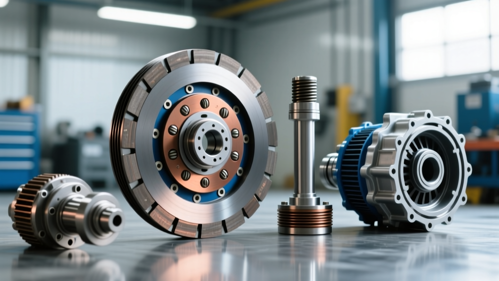
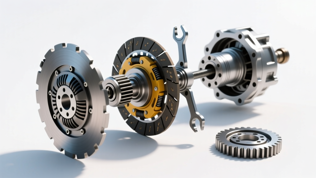
Unlike light-duty passenger vehicles, heavy-duty systems—such as those paired with the Eaton Fuller FRO-16210C or the Tremec TR-4050—utilize massive friction surfaces and complex torsional damping. A standard manual transmission clutch diagram for a commercial rig will highlight components such as 15.5-inch dual-plate assemblies, intermediate drive plates, and multi-stage torsional dampers. These dampers are essential for absorbing the low-frequency, high-amplitude torque spikes produced by large-displacement diesel engines like the Cummins X15 or the Detroit Diesel DD15.
Diagnostic Symptoms: Identifying Heavy-Duty Clutch Failures
Symptoms in commercial applications often manifest differently than in standard pickup trucks. The immense clamping force required to hold 1,800+ lb-ft of torque places extraordinary stress on the pressure plate fingers, release bearings, and flywheel friction surfaces.
Torsional Damper Failure and Driveline Chatter
If your commercial vehicle exhibits violent shuddering upon engagement from a dead stop, the torsional dampers inside the clutch disc have likely bottomed out or shattered. In heavy-duty PTO (Power Take-Off) applications, the sudden load reversals can fatigue the damper springs. When reviewing the manual transmission clutch diagram, note the location of the inner and outer damper springs; if the disc shows signs of radial cracking near the hub, immediate replacement with an upgraded multi-stage damper disc is required.
Thermal Glazing and Load Slipping
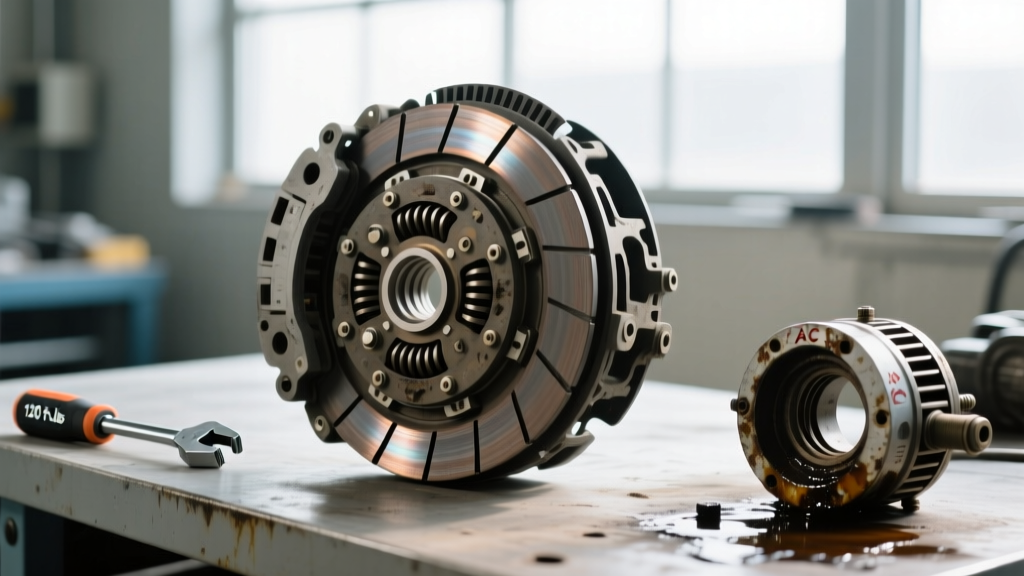
Slipping on steep grades or during heavy towing is a hallmark of thermal glazing. Organic friction materials begin to degrade and lose their coefficient of friction at temperatures exceeding 500°F (260°C). Once glazed, the clutch disc develops a hardened, glass-like surface that cannot be sanded off. In Class 8 trucks, this often necessitates replacing the entire Eaton Solo Advantage assembly, as the extreme heat also warps the intermediate plates and anneals the pressure plate springs.
Release Bearing and Clutch Brake Squeeze Issues
Heavy-duty manual transmissions utilize a clutch brake to stop the input shaft for smooth shifting. If the pedal free-play is improperly adjusted, the release bearing may ride constantly against the clutch brake, causing premature failure. Proper adjustment requires exactly 0.500" to 0.625" of clutch brake squeeze at the firewall.
| Failure Mode | Primary Symptom | Diagram Component Affected | Upgrade Solution |
|---|---|---|---|
| Torsional Fatigue | Violent chassis chatter on engagement | Damper Springs / Hub Spline | Multi-Stage Poly-Dampened Disc |
| Thermal Glazing | RPM flare under heavy load / towing | Friction Disc / Intermediate Plate | Cerametallic or Sintered Iron Disc |
| Clutch Brake Drag | Hard shifting, bearing whine | Release Bearing / Clutch Brake | Heavy-Duty HD Bearing & Firewall Adjust |
| Spline Shearing | Sudden loss of drive, grinding noise | Disc Hub / Input Shaft | 2.0" 10-Spline Chromoly Hub Upgrade |
Performance Upgrades: Moving Beyond OEM Friction Limits
When OEM organic clutches fail under the stress of commercial towing or upfit equipment usage, upgrading the friction material is mandatory for long-term reliability. The manual transmission clutch diagram serves as your blueprint for ensuring the upgraded components maintain proper clearances within the bell housing.
Cerametallic vs. Sintered Iron: Choosing the Right Material
For heavy-duty commercial pickups (like the Ford F-550 or Ram 4500) and Class 8 tractors, friction material choice dictates drivability and holding power:
- Cerametallic (Cera-Metallic): Offers a high coefficient of friction (0.45 to 0.55) and exceptional thermal resistance up to 1,000°F. Ideal for heavy towing and frequent stop-and-go commercial routes. Kits like the South Bend DD3250-6 utilize cerametallic buttons that provide aggressive bite without the extreme pedal effort of solid hubs.
- Sintered Iron: The ultimate choice for Class 8 highway tractors and severe-duty PTO applications. Sintered iron handles massive torque loads (2,000+ lb-ft) and is virtually immune to thermal fade. However, it requires a machined steel flywheel surface and results in a very abrupt, on/off engagement that is unsuitable for light-duty maneuvering.
Precision Installation: Torque Specs and Step Heights
Replacing a heavy-duty clutch requires strict adherence to engineering tolerances. The splines on commercial input shafts are significantly larger—typically 1.75" x 10-spline or 2.0" x 10-spline—requiring specialized alignment tools. Furthermore, when installing dual-plate setups, verifying the flywheel step height is critical. An incorrect step height will result in the intermediate plate floating, causing severe chatter and premature wear.
Critical Torque and Clearance Specifications
Always refer to the manufacturer's specific manual transmission clutch diagram for your exact application, but the following baseline specifications apply to most heavy-duty diesel applications (e.g., Cummins ISX, Ford 6.7L Powerstroke, Detroit DD13):
| Component | Specification / Measurement | Notes |
|---|---|---|
| Flywheel to Crankshaft | 120 - 150 lb-ft (Engine Dependent) | Use new OEM stretch bolts; apply thread locker. |
| Pressure Plate to Flywheel | 35 - 50 lb-ft (Star Pattern) | Incrementally tighten in 3 passes to prevent warping. |
| Dual-Disc Flywheel Step Height | 0.030" - 0.050" (Typical) | Must be machined if out of spec; do not use shims. |
| Pedal Free Play | 1.5" - 2.0" at the pedal pad | Ensures release bearing does not ride on fingers. |
| Clutch Brake Squeeze | 0.500" - 0.625" at firewall | Critical for heavy-duty unsynchronized shifting. |
Sourcing and Cost Breakdown for Fleet Upgrades
Upgrading a commercial vehicle's clutch system is a significant capital expenditure, but it prevents catastrophic roadside failures. Pricing varies heavily based on the Gross Vehicle Weight Rating (GVWR) and the specific transmission mating.
- Heavy-Duty Pickup Upgrades (Class 3-4): A high-quality dual-disc cerametallic kit (e.g., South Bend or Valair) ranges from $1,200 to $2,400. Add a billet steel flywheel for an additional $600 to $900.
- Class 8 Highway Tractors (Eaton Fuller): A 15.5-inch Solo Advantage replacement clutch assembly typically costs between $1,800 and $3,200. Sintered iron upgrade discs add roughly $400 to the parts cost.
- Labor and Downtime: Dropping a heavy-duty transmission requires specialized shop equipment (transmission jacks rated for 500+ lbs). Expect labor costs to range from $1,500 to $2,800, representing 12 to 20 hours of shop time.
By thoroughly studying the manual transmission clutch diagram and understanding the specific failure modes of commercial drivetrains, fleet managers and owner-operators can spec the right upgraded components, ensuring maximum uptime and superior torque transfer for the most demanding jobs on the road.