The Critical Role of Line Routing in Auxiliary Cooler Installs
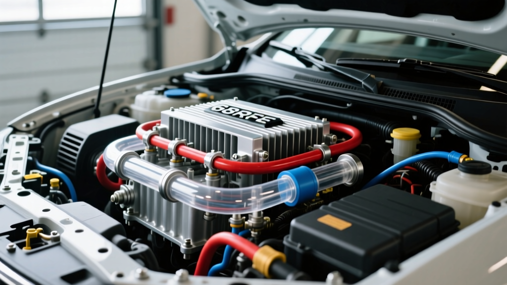
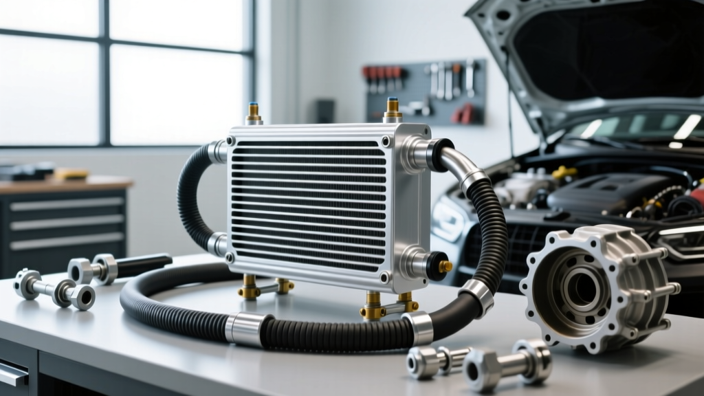
When enthusiasts and professional mechanics upgrade their transmission cooling capacity, the Hayden 679 transmission cooler is frequently the hardware of choice. Rated for up to 26,000 lbs Gross Vehicle Weight (GVW), this 11-inch by 9.5-inch plate-and-fin cooler offers exceptional thermal transfer for light-duty towing, off-road crawling, and high-stress street applications. However, bolting a high-efficiency cooler to the front of a radiator is only half the battle. The true bottleneck in any thermal management system lies in the plumbing.
Improper transmission cooler line routing introduces parasitic pressure drops, flow restrictions, and catastrophic leak points. In modern transmissions like the GM 6L80 or the venerable 4L60E, the cooler circuit is not just about dropping fluid temperatures; it is an integral part of the transmission lubrication and torque converter charge circuit. A kinked or poorly routed return line can starve the planetary gearsets of oil, leading to immediate mechanical failure regardless of how efficiently the cooler itself operates. In this 2026 expert guide, we break down the exact methodologies for routing, clamping, and integrating the Hayden 679 into your vehicle's drivetrain.
Mapping the Flow: Series vs. Standalone Integration
Before cutting a single length of hose, you must define the flow architecture. The most common mistake in auxiliary cooler installations is routing the external cooler in parallel with the OEM radiator cooler or bypassing the radiator entirely for daily-driven vehicles.
Why Series Routing is Non-Negotiable for Daily Drivers
For 95% of applications, the Hayden 679 transmission cooler must be installed in series with the factory radiator heat exchanger. The correct flow order is:
- Transmission OUT (Hot fluid to OEM radiator cooler)
- OEM Radiator OUT to Hayden 679 IN
- Hayden 679 OUT to Transmission IN (Return port)
The factory radiator acts as a thermal thermostat. In cold climates or during winter commuting, transmission fluid needs to reach roughly 160°F to 180°F to vaporize condensed moisture and maintain optimal hydraulic viscosity. If you route the Hayden 679 standalone, the fluid will overcool, leading to sluggish valve body shifts and accelerated clutch wear. By placing the 679 after the radiator, the radiator warms the fluid on cold days, and on hot days under heavy towing, the Hayden 679 strips the remaining heat load before the fluid returns to the pan.
Hose Selection and Fitting Standards for the Hayden 679
The Hayden 679 utilizes standard 11/32-inch or 3/8-inch hose barb fittings depending on the specific adapter kit used. Selecting the correct hose material is where most DIY installations fail. Standard fuel line or generic rubber hose will rapidly degrade when exposed to the extreme heat and chemical composition of modern synthetic automatic transmission fluids (ATF) like Dexron ULV or ACDelco ATF+4.
| Component | Required Specification | Engineering Rationale |
|---|---|---|
| Hose Material | SAE J1532 Transmission Oil Cooler Hose | Specifically compounded to resist synthetic ATF degradation and sustained 150°C+ temperatures without softening or blistering. |
| Hose Clamps | Fuel Injection (FI) Clamps | FI clamps feature rolled edges that grip evenly without slicing into the soft outer jacket of ATF cooler hoses. |
| Mounting Hardware | Adel Clamps (P-Clips) with Rubber Cushion | Prevents chassis vibration from wearing through the hose jacket over thousands of miles. |
| Zip Ties | UV-Rated, High-Temp Nylon 6/6 (Avoid for primary mounting) | Standard zip ties become brittle and snap under hood heat cycles. Use only for temporary wire management, never for securing pressurized ATF lines. |
The Danger of Worm-Gear Clamps
Never use standard worm-gear (hose) clamps on transmission cooler lines. The slotted band of a worm-gear clamp acts like a cheese grater on SAE J1532 hose when subjected to the thermal expansion and contraction of engine bay heat cycles. Over time, the clamp cuts through the outer reinforcement braid, leading to slow seepage. A loss of just one quart of ATF can drop line pressure enough to cause clutch slip in a 4L60E. Always use rolled-edge Fuel Injection clamps, torqued to approximately 15-25 in-lbs using a 1/4-inch drive torque wrench.
Step-by-Step Routing Best Practices and Clearances
Routing the lines from the transmission to the front bumper or grille support requires navigating a minefield of steering shafts, exhaust manifolds, and suspension components. Follow these strict clearance and bend radius rules:
- The 3-Inch Exhaust Rule: Maintain a minimum of 3 inches of clearance between any ATF hose and exhaust components (headers, catalytic converters, or exhaust pipes). Radiant heat from exhaust components can exceed 400°F, which will bake the rubber hose from the outside in, causing internal delamination that blocks fluid flow.
- Minimum Bend Radius: SAE J1532 hose requires a minimum bend radius of 2.5 inches. Bending the hose tighter than this will cause the internal wall to collapse. A collapsed hose acts as a severe hydraulic orifice, dropping return line pressure and causing torque converter drain-back, which results in delayed forward engagement upon startup.
- Adel Clip Spacing: Secure the hose using rubber-cushioned Adel clamps (P-clips) every 12 to 18 inches. This prevents the hose from whipping against the frame rails during high-RPM shifts or off-road articulation.
- Chafe Protection: Where lines must pass through the radiator core support or firewall, use split-loom tubing or dedicated rubber grommets. Aluminum core supports will slice through a pressurized ATF line in less than 50 miles due to engine rock.
Real-World Application: Managing Line Pressures in Modern Transmissions
Understanding the hydraulic environment of your specific transmission is vital when routing lines to the Hayden 679. For example, the GM 6L80 and 6L90 transmissions utilize a variable displacement pump that can push line pressures up to 260 PSI under heavy load or in reverse. Conversely, the older 4L60E typically operates between 100 and 140 PSI in forward gears.
Expert Insight: When routing lines on a 6L80, the high-pressure spikes during aggressive downshifts can blow poorly seated hoses right off the cooler barbs. Always push the hose onto the Hayden 679 barb until it bottoms out against the raised shoulder, and utilize dual FI clamps on the return side if operating in high-stress towing environments.
Furthermore, plate-and-fin coolers like the Hayden 679 inherently create slightly more flow restriction than massive tube-and-fin coolers due to the turbulent flow required inside the plates to maximize heat transfer. To compensate for this, ensure your hard lines (the metal pipes running from the transmission) are free of internal rust or scale. If your vehicle has over 100,000 miles, flush the hard lines with a dedicated solvent before connecting the new rubber hoses to prevent debris from clogging the narrow fins of the 679.
Common Routing Mistakes That Destroy Transmissions
Even with the right parts, poor execution can ruin a drivetrain. Avoid these frequent errors:
1. Reversing Flow Direction
While some plate-and-fin coolers are multi-pass and theoretically flow-agnostic, Hayden Automotive recommends specific flow orientations to prevent air entrapment. Always look for the 'IN' and 'OUT' stampings on the Hayden 679 mounting plate. Feeding fluid in the top and out the bottom helps gravity assist in purging air pockets during the initial fill.
2. Airlocking the System
The Hayden 679 and its associated hoses hold roughly 1 to 1.5 quarts of additional fluid. If you do not properly bleed the system, a massive air pocket will circulate through the transmission upon first startup. This aerated fluid is compressible and will result in instant clutch burnout due to a lack of hydraulic clamping force. After routing and filling, idle the vehicle in park with the parking brake engaged, cycle through the gears slowly, and check the dipstick until the fluid level stabilizes and no bubbles are visible.
3. Routing Through the Fan Shroud Improperly
When passing hoses through the factory fan shroud to reach the transmission, never route them near the mechanical or electric cooling fans. A slight engine mount deflection under heavy throttle can push the engine backward just enough for a spinning fan blade to catch an ATF line, instantly draining your transmission fluid onto a hot exhaust. Always route lines below the fan arc or through dedicated factory notches.
Final Verification and Maintenance
Once the Hayden 679 transmission cooler is mounted and the lines are routed, perform a thermal cycle test. Drive the vehicle until the transmission fluid reaches normal operating temperature (180°F - 200°F). Park the vehicle and inspect every hose barb and clamp while the system is fully pressurized and hot. Look for micro-seepage. For comprehensive installation diagrams and torque specifications, always refer to the Hayden Automotive Tech Resources library, and verify hose compatibility using the Gates Automotive Hose Catalog. Proper routing is not just about aesthetics; it is the lifeline of your transmission's longevity.