Understanding the Auto Locking Mechanism
Rebuilding an auto locking rear differential requires a fundamentally different approach than servicing a standard open carrier or a clutch-type limited-slip differential (LSD). The most ubiquitous auto locking rear differential in the North American light truck market is the Eaton G80, found in millions of GM trucks and SUVs (Silverado, Sierra, Tahoe, Suburban) featuring the 8.5-inch and 8.6-inch 10-bolt, as well as the 14-bolt semi-floating axles. Unlike clutch-pack LSDs that rely on hydraulic pressure and friction modifiers to transfer torque, the G80 utilizes a mechanical flyweight governor and a locking pawl. When wheel spin exceeds a predetermined threshold (typically 100 RPM difference between the left and right axles), the flyweights swing outward, catch a latching bracket, and force a self-energizing clutch to lock the side gears to the carrier case instantly.
Because this mechanism relies on precise mechanical clearances rather than clutch friction, rebuilding an auto locking rear differential demands strict adherence to metrology, bearing preload specifications, and governor spring tension. A botched rebuild will result in either a failure to lock under slip conditions or a violent, driveline-shattering engagement on dry pavement. This step-by-step guide details the complete teardown, inspection, and reassembly of the GM 10-bolt (8.5/8.6) G80 differential.
Essential Tools and OEM Part Numbers
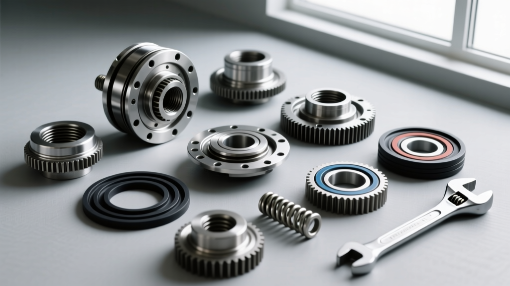
Before splitting the differential cover, gather the necessary precision tools and replacement components. Do not reuse crush sleeves, ring gear bolts, or carrier bearings.
- Bearing Kit: Timken LM501349 (Cone) and LM501311 (Cup) for the carrier; Timken LM102949/LM102910 for the pinion (verify with your specific axle RPO code).
- Seal & Crush Sleeve Kit: Includes a new pinion seal, crush sleeve, and pinion nut.
- Threadlocker: Loctite 272 (High-Strength Red) for ring gear bolts.
- Precision Tools: 0-50 in-lb dial torque wrench (for pinion preload), 1/2-inch drive ft-lb torque wrench, dial indicator with magnetic base, and a hydraulic press with bearing splitter plates.
- Gear Oil: 75W-90 Full Synthetic (e.g., ACDelco 10-4016 or Mobil 1 104361). Crucial Note: Never add friction modifier to an auto locking rear differential.
Phase 1: Safe Teardown and Component Extraction
Proper teardown is critical for establishing baseline measurements and ensuring components return to their original orientations.
- Drain and Extract: Remove the differential cover and drain the fluid. Inspect the fluid for metallic glitter (indicating bearing wear) or chunky shavings (indicating gear tooth or governor failure).
- Mark the Bearing Caps: Use a steel stamp or paint pen to match-mark the bearing caps to the carrier housing. These caps are line-bored at the factory; swapping them left-to-right will destroy the bearing alignment and cause immediate catastrophic failure.
- Remove the Carrier: Unbolt the bearing caps and carefully pry the carrier assembly out using a pry bar positioned between the housing and the carrier bearing, taking care not to score the bearing journals.
- Extract the Pinion: Remove the driveshaft yoke, noting the pinion nut thread size. Use an impact wrench to remove the pinion nut, then press the pinion gear out through the rear of the housing using a hydraulic press.
Phase 2: Metrology and Wear Inspection
The G80 governor mechanism is highly sensitive to internal contamination and wear. Inspect all components against the factory specifications outlined in Eaton's official differential documentation.
| Component | Specification / Wear Limit | Action Required |
|---|---|---|
| Ring Gear Runout | Less than 0.003 inches | Remount ring gear or replace if warped |
| Backlash (Ring & Pinion) | 0.006 to 0.010 inches | Adjust via carrier side shims during assembly |
| Governor Flyweights | Free movement, zero galling on pins | Replace entire governor assembly if binding occurs |
| Locking Pawl & Latching Bracket | Sharp, defined edges; no rounding | Replace if edges are rounded (causes slipping under load) |
| Pinion Bearing Preload | 15 to 25 in-lbs (New Bearings) | Adjust via crush sleeve compression |
If the flyweights show signs of scoring, or if the latching bracket teeth are rounded, the differential will fail to engage when wheel slip occurs. Consult resources like Randy's Ring & Pinion Tech Tips for visual examples of G80 governor wear patterns.
Phase 3: Pinion Depth and Bearing Preload Setup
Setting the pinion depth is the most mathematically rigorous part of any differential rebuild. The pinion depth dictates how deeply the pinion gear meshes with the ring gear, directly affecting the contact pattern and gear whine.
Step 1: Pinion Depth Shimming
Remove the inner pinion bearing cone and install a 'setup bearing' (a bearing with the inner diameter honed out slightly so it slides on and off the pinion shaft by hand). Install the pinion into the housing without the pinion seal or crush sleeve. Use a pinion depth gauge to measure the variance from the factory-specified depth (usually etched on the pinion head, e.g., '+2' or '-1'). Add or subtract shims behind the inner bearing cup until the dial indicator reads zero variance.
Step 2: Setting Pinion Preload
Once the depth is set, press on the new, final inner and outer Timken automotive bearings. Install a new crush sleeve and the pinion yoke. Tighten the pinion nut incrementally while checking the rotational torque with an inch-pound dial wrench. You are crushing the sleeve to achieve exactly 15 to 25 in-lbs of rotational drag. Warning: If you over-tighten and exceed 25 in-lbs, you must install a brand new crush sleeve and start over. Never back off the pinion nut to reduce preload.
Phase 4: Carrier Assembly and G80 Governor Integration
With the pinion set, attention turns to the carrier and the auto locking mechanism.
- Ring Gear Mounting: Clean the ring gear mating surface and the carrier flange with brake cleaner. Apply a thin bead of Loctite 272 to the threads of the new ring gear bolts. Heat the ring gear in an oven to 200°F to expand it, drop it onto the carrier, and torque the bolts to 70 ft-lbs in a crisscross star pattern.
- G80 Governor Assembly: Assemble the locking pawl, flyweights, and governor spring into the carrier case window. Ensure the return spring provides adequate tension to snap the flyweights back to their resting position instantly when wheel speeds equalize. Lubricate the governor pins with a small amount of 75W-90 gear oil.
- Setting Backlash and Pattern: Press the new carrier bearings onto the carrier journals. Install the carrier into the housing with the appropriate side shims to achieve 0.006 to 0.010 inches of backlash. Apply yellow gear marking compound to the ring gear teeth and rotate the assembly under slight drag. The pattern should be centered on the tooth face, slightly biased toward the toe on the drive side. Adjust pinion depth (drive side pattern) and backlash (coast side pattern) as necessary.
- Final Torque: Reinstall the line-bored bearing caps in their exact original orientation and torque the cap bolts to 60 ft-lbs.
Phase 5: Fluid Specifications and Break-In Protocol
The final and most frequently botched step in an auto locking rear differential rebuild is the fluid fill. The Eaton G80 requires standard 75W-90 Synthetic GL-5 gear oil. The capacity for a GM 10-bolt 8.5/8.6 axle is approximately 2.1 to 2.5 quarts, depending on the cover design.
The Friction Modifier Trap: Many technicians mistakenly add a limited-slip friction modifier (like GM EOS or Ford XL-3) because they are accustomed to clutch-type LSDs. Doing this in an auto locking rear differential reduces the friction coefficient of the internal self-energizing clutch pack. This will cause the G80 to slip under heavy load or fail to lock entirely. Fill the axle with pure 75W-90 synthetic gear oil until it reaches the bottom of the fill hole.
Break-In Procedure: For the first 500 miles, avoid sustained highway speeds and heavy towing to allow the new bearings and gear teeth to mate. Perform 10 to 15 controlled locking events on a loose surface (like gravel or wet grass) by inducing mild wheel spin. This ensures the governor flyweights and locking pawl seat properly and cycle smoothly before the axle is subjected to high-torque dry-pavement loads. After the 500-mile break-in, consider draining and refilling the fluid to remove any initial microscopic assembly debris, ensuring decades of reliable, automatic locking performance.