Bridging Drivetrain and Accessory Clutch Diagnostics
At AutoGearNexus, our core expertise lies in transmission and drivetrain friction clutches, such as the complex internal clutch packs found in Ford's 10R140 automatic transmission. However, the fundamental principles of clutch system diagnostics—evaluating engagement, slip, fluid dynamics, and electromagnetic actuation—apply equally to heavy-duty accessory drives. When dealing with 6.7 powerstroke fan clutch problems, technicians must pivot from analyzing transmission fluid shear to evaluating high-viscosity silicone fluids and Pulse Width Modulation (PWM) solenoids. This technical deep-dive provides a comprehensive clutch system inspection checklist tailored specifically for the Ford 6.7L Powerstroke diesel engine's cooling fan drive.
Understanding the 6.7L Powerstroke Fan Clutch Mechanism
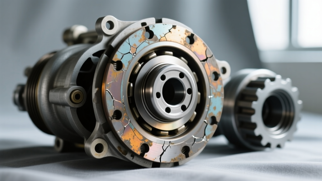
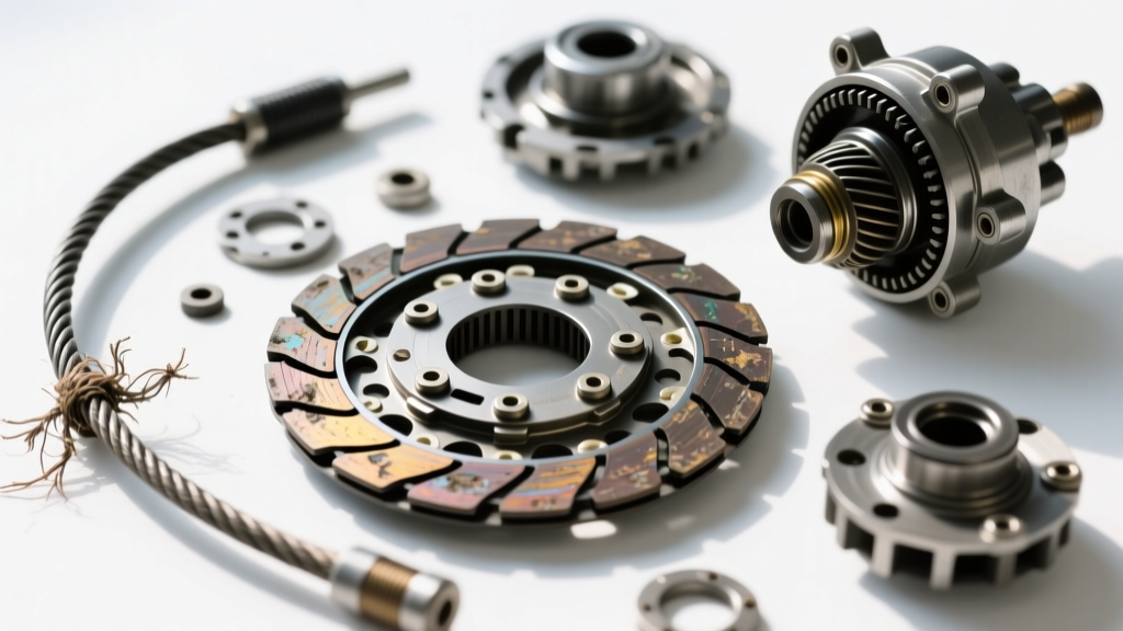
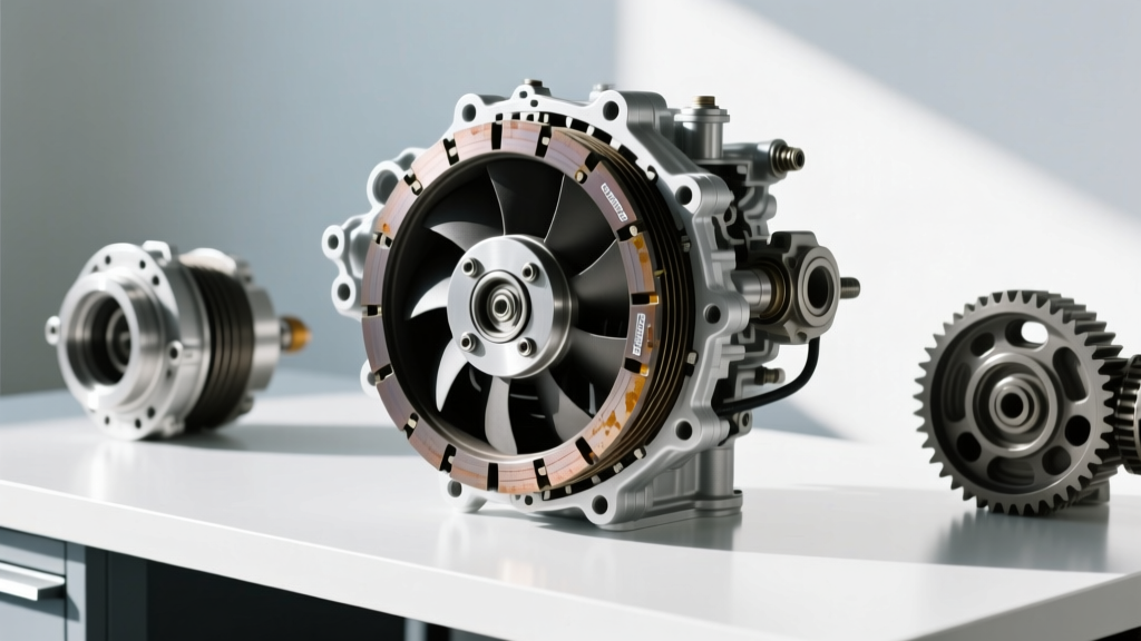
Unlike a traditional manual transmission clutch that relies on mechanical friction plates, the 6.7L Powerstroke utilizes a viscous-electronic fan clutch. This component acts as a fluid coupling. Inside the sealed housing, a rotor is driven by the engine's serpentine belt via the water pump hub. The housing, which holds the fan blade, is driven by the rotor through a specialized high-viscosity silicone fluid.
Modern 6.7L Powerstroke models use an electronically controlled viscous clutch. The Powertrain Control Module (PCM) monitors engine coolant temperature (ECT), intake air temperature (IAT), and A/C head pressure. It then sends a PWM signal to an electromagnetic solenoid on the fan clutch. This solenoid opens a micro-valve, allowing silicone fluid to transfer between the reservoir and the working chamber, thereby increasing the lock-up ratio and pulling more air through the radiator and intercooler.
The Master Clutch System Inspection Checklist
Before condemning the component or tearing down the front-end accessory drive (FEAD), run through this structured diagnostic checklist. This framework isolates mechanical, hydraulic (viscous), and electrical failure modes.
| Inspection Phase | Diagnostic Action | Pass Criteria / Expected Result | Failure Indicator |
|---|---|---|---|
| Visual / Mechanical | Check for silicone fluid weeping around the hub seal and bimetallic strip/solenoid housing. | Dry exterior; minor dust accumulation is normal. | Greasy residue or visible fluid slinging on the shroud. |
| Visual / Mechanical | Check bearing play by rocking the fan blade laterally. | Zero to minimal lateral deflection (< 0.050 inches). | Audible grinding, rough rotation, or excessive wobble. |
| Cold State (Viscous) | Rotate fan blade by hand with engine OFF and COLD. | Smooth rotation with consistent, light viscous drag. | Completely free-spinning (fluid loss) or locked solid (internal seizure). |
| Hot State (Viscous) | Monitor fan RPM via OBD-II scanner while engine reaches operating temp (190°F+). | Fan RPM increases proportionally with ECT and A/C demand. | Fan RPM remains at base idle speed; ECT spikes under load. |
| Electrical (Solenoid) | Measure solenoid coil resistance at the pigtail connector. | Typically 10.0 to 15.0 Ohms at 68°F (20°C). | Open circuit (OL) or short to ground. |
| Electrical (Signal) | Back-probe the PWM control wire with an oscilloscope or advanced multimeter. | Clean square wave pattern; frequency ~100-200 Hz, varying duty cycle. | Flatlined voltage or erratic duty cycle outside PCM parameters. |
Step-by-Step Diagnostic Procedure
1. The Cold Spin and Auditory Test
With the engine cold and off, attempt to spin the fan blade. A healthy viscous clutch will offer a smooth, uniform resistance. If the fan spins completely freely without any drag, the internal silicone fluid (typically rated between 10,000 and 60,000 centistokes) has leaked out or severely degraded due to thermal shearing. Conversely, if the fan is locked solid and cannot be turned by hand, the internal rotor-to-housing clearance (normally 0.020" to 0.040") has collapsed, or the fluid has crystallized from extreme overheating.
Technician's Note: Never use excessive force to turn a locked viscous clutch. You risk transferring the torsional load directly into the water pump bearings, causing catastrophic coolant system failure.
2. Electronic Solenoid and Circuit Verification
If the mechanical spin test passes, the issue likely lies in the electronic actuation. Disconnect the electrical connector at the fan clutch. Using a digital multimeter (DMM), measure the resistance across the two terminals of the clutch-side solenoid. According to Motorcraft engineering specifications, an out-of-range reading (typically below 8 Ohms or above 20 Ohms) indicates a burnt internal coil.
Next, check the chassis-side wiring. The 6.7L Powerstroke is notorious for harness chafing near the fan shroud and radiator support. Inspect the wiring for brittleness or exposed copper. If the PCM detects an open or shorted circuit, it will often default the fan to a failsafe 'limp' mode (usually locked at a medium-high speed) or disable it entirely, triggering a Check Engine Light with codes like P052A (Cold Start Fan Speed Control) or P052B.
3. Active Command and Thermal Load Testing
Connect a bi-directional OBD-II scan tool capable of accessing the Ford PCM. Command the fan clutch duty cycle from 10% up to 90% while the engine is idling. You should hear a distinct change in engine acoustics and airflow within 3 to 5 seconds of altering the command. If the scan tool commands 85% duty cycle but the fan RPM PID does not increase, the internal micro-valve is clogged with degraded silicone particulate, or the electromagnetic armature is failing to pull the valve pin.
Common 6.7 Powerstroke Fan Clutch Problems
- Fluid Shearing and Degradation: Towing heavy 5th-wheel loads up steep grades (e.g., the Ike Gauntlet) generates immense under-hood heat. Over time, this bakes the silicone fluid, causing it to lose its shear strength. The clutch will slip excessively, leading to elevated EGTs and coolant temperatures.
- Bearing Seizure: The front bearing of the fan clutch assembly supports the entire weight of the composite fan blade. When the seal fails and moisture contaminates the bearing, it creates a high-pitched whine. This is frequently misdiagnosed as a failing transmission torque converter or a whining power steering pump.
- PCM Calibration Issues: Early 2011-2014 6.7L Powerstrokes had known PCM calibration bugs where the fan clutch engagement logic was too conservative, leading to overheating while idling in traffic. A PCM flash via the Ford FDRS system is sometimes required before replacing hard parts.
OEM vs. Aftermarket Replacement Data
When 6.7 powerstroke fan clutch problems necessitate a replacement, selecting the correct component is critical for maintaining the precise thermal management required by the 6.7L diesel. Below is a comparative analysis of replacement options available in the current market.
| Brand / Type | Part Number (Reference) | Estimated Cost (USD) | Warranty / Notes |
|---|---|---|---|
| OEM Motorcraft | BC3Z-8A616-A (11-14) / FC3Z-8A616-A (15+) | $450 - $650 | 2-Year Unlimited Mileage. Exact factory PWM calibration. |
| Horton (Heavy Duty) | Various Kysor/Horton equivalents | $500 - $700 | Often used in commercial/motorhome applications. Superior fluid capacity. |
| Aftermarket (Dorman/Others) | Various generic replacements | $250 - $350 | 1-Year Limited. Higher risk of solenoid failure and PWM mismatch. |
For further community-tested reliability data and part cross-references, consult the archives at Ford-Trucks.com and specialized heavy-duty cooling forums.
Installation and Torque Specifications
Replacing the fan clutch on a 6.7L Powerstroke requires specialized tooling due to the massive torque required to secure the hub. The fan clutch assembly threads onto the water pump hub. Depending on the exact model year, this is typically a large M36 or similar fine-thread nut.
Critical Torque Specs:
- Fan Clutch to Water Pump Hub Nut: 85 lb-ft (115 Nm). Note: This often requires a specialized fan clutch holding wrench (e.g., OTC 6612 or equivalent) and a long-breaker bar. Some model years utilize a left-hand thread; always verify rotation direction before applying breaking torque.
- Fan Blade to Clutch Housing Bolts: 22 lb-ft (30 Nm). Ensure the composite fan blade is indexed correctly to avoid imbalance vibrations at high RPM.
Final Diagnostic Thoughts
Diagnosing 6.7 powerstroke fan clutch problems requires a methodical approach that bridges mechanical inspection with electronic network analysis. By utilizing this clutch system inspection checklist, technicians can confidently isolate whether the failure stems from viscous fluid degradation, bearing collapse, or a PCM/solenoid electrical fault. Proper diagnosis not only saves the customer from unnecessary parts swapping but ensures the 6.7L Powerstroke maintains optimal thermal efficiency under the most grueling towing conditions.
For more deep-dives into Ford's drivetrain and accessory systems, including the 10R140 transmission clutch pack tolerances and torque converter diagnostics, continue exploring our technical library at AutoGearNexus.