The Hidden Threat Inside Your Automatic Transmission Cooler
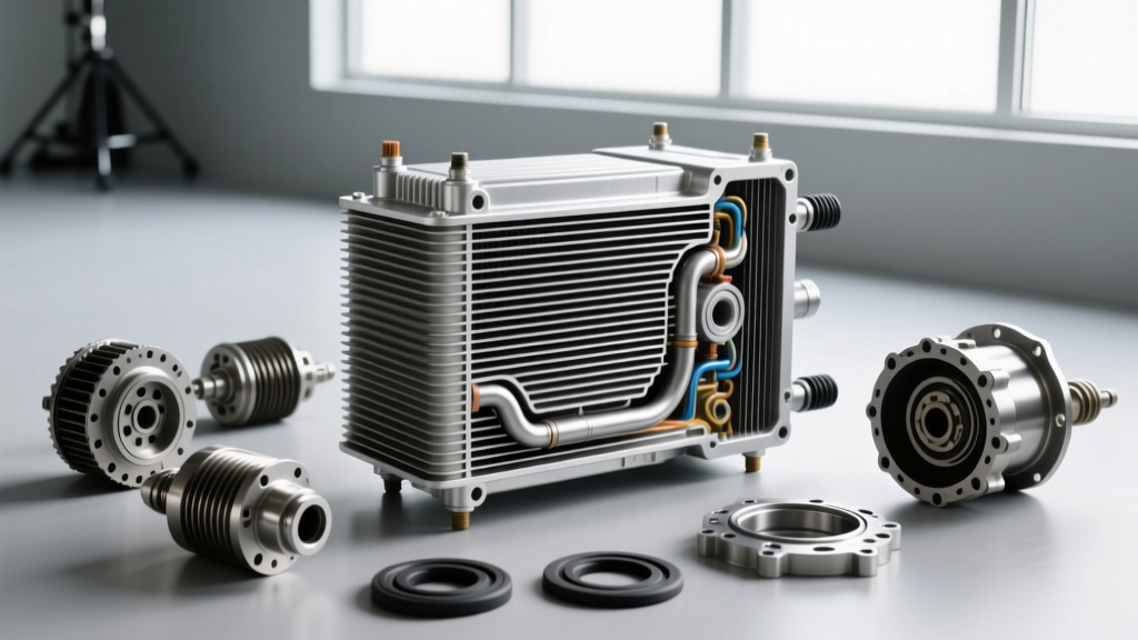
As we navigate the 2026 automotive landscape, modern 8-speed and 10-speed automatic transmissions operate under immense thermal stress. The automatic transmission cooler is the primary defense against fluid degradation, yet it is often the most neglected component in preventive maintenance. Over time, oxidized transmission fluid forms a varnish-like sludge that coats the internal turbulators of stacked-plate coolers and restricts the micro-channels of tube-and-fin designs. This restriction starves the transmission of vital lubrication and cooling, leading to clutch glazing, torque converter shudder, and ultimately, catastrophic failure.
A proper transmission cooling system flush is not merely a fluid swap; it is a targeted hydraulic cleaning procedure designed to restore optimal flow dynamics and thermal exchange efficiency. This guide details the exact diagnostic metrics, procedural steps, and torque specifications required to service the cooler circuits of popular platforms like the GM 6L80/8L90, Ford 10R80, and ZF 8HP series.
Diagnosing a Restricted Cooler Circuit
Before connecting a flush machine, you must establish a baseline to confirm whether the cooler is actually restricted. Guesswork leads to unnecessary labor. Professional drivetrain technicians rely on two primary diagnostic metrics: Pressure Drop Testing and Delta-T Thermal Analysis.
1. Pressure Drop Testing
Install an inline hydraulic pressure gauge (0-100 psi range) between the transmission cooler output line and the radiator return port. Start the engine and measure the pressure drop across the cooler circuit.
- Normal Idle (700 RPM): Pressure drop should be less than 5 psi.
- Stall/2000 RPM: Pressure drop should not exceed 12-15 psi.
- Failure Threshold: A pressure drop exceeding 20 psi at 2000 RPM indicates severe varnish buildup or a collapsed internal cooler hose. Immediate flushing or replacement is required.
2. Delta-T Thermal Analysis
Using an infrared thermometer or OBD2 bi-directional scanner to read the Transmission Fluid Temperature (TFT) PID, measure the fluid temperature entering the cooler and exiting the cooler under a steady highway load. A healthy automatic transmission cooler will exhibit a Delta-T (temperature drop) of 30°F to 50°F (16°C to 28°C). If the Delta-T is less than 15°F, flow is restricted, or the thermal bypass valve is stuck in the open position, routing hot fluid directly back to the pan.
Required Tools and Fluid Specifications
Modern ultra-low viscosity (ULV) fluids require strict adherence to OEM specifications. Cross-contamination during a flush can cause immediate shift adaptation failures.
- Flush Equipment: Pneumatic-assisted fluid exchange machine (e.g., BG PF7 or Lubegard FEX) with variable flow control.
- GM Applications (6L80/8L90): ACDelco Dexron ULV (Part # 19417577).
- Ford Applications (10R80): Motorcraft MERCON ULV (Part # XT-12-QULV).
- ZF 8HP Applications: ZF LifeguardFluid 8 or Shell ATF 134FE.
- Hand Tools: Line wrench set (metric and SAE), digital torque wrench, OBD2 scanner with live TFT data logging.
Step-by-Step Cooler Flush Procedure
Warning: Never use raw compressed air from a shop compressor to blow out cooler lines. Tube-and-fin coolers (like the Derale 15800 series) utilize soft solder joints at the end caps. Pressures exceeding 30 psi can easily rupture these joints, causing internal coolant-to-ATF cross-contamination.
- Thermal Bypass Verification: Modern transmissions utilize a thermal bypass valve to speed up cold-start warm-ups. This valve typically opens at 185°F - 190°F (85°C - 88°C). If the valve is stuck closed, the cooler is entirely bypassed. Use your OBD2 scanner to verify that cooler flow initiates once the TFT PID crosses the 190°F threshold. If it does not, replace the bypass valve (e.g., GM part # 24296663 or Sonnax heavy-duty bypass delete kit) before flushing.
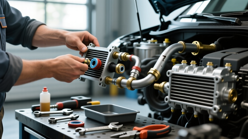
- Line Disconnection: Disconnect the cooler return line at the transmission case. Cap the transmission port to prevent debris ingress. Route the disconnected line into a calibrated drain pan.
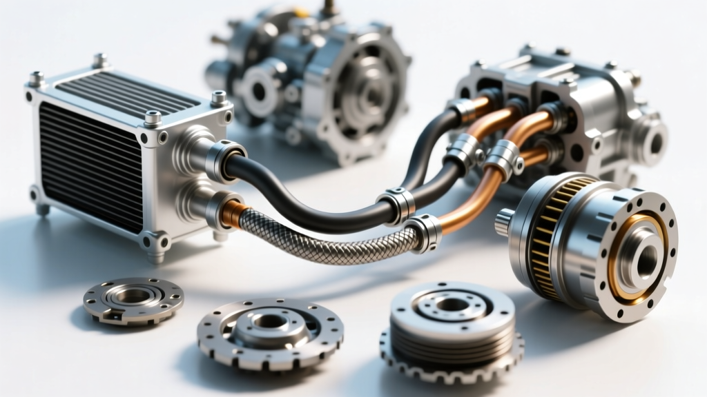
- Machine Integration: Connect the flush machine in-line with the cooler feed and return lines at the radiator. Ensure the machine's flow direction matches the OEM hydraulic routing (typically out of the transmission, into the cooler, and back).
- The Exchange Cycle: Initiate the flush. For heavily degraded systems, introduce a specialized transmission cooler flush solvent (like Lubegard 98901) into the machine's reservoir. Allow the solvent to cycle through the cooler for 10 minutes at idle to break down varnish.
- Final Fluid Exchange: Switch the machine to fresh OEM fluid. Cycle a minimum of 1.5 times the total system capacity (e.g., if the transmission holds 11 quarts, push at least 16 quarts of new fluid through the system) to ensure all solvent and suspended particulates are evacuated.
- Reconnection and Torque: Reconnect the cooler lines using new crush washers or O-rings. Apply the exact torque specifications listed below.
Cooler Line Torque Specs and Reassembly Data
Overtightening cooler line fittings is a leading cause of hairline fractures in aluminum transmission cases and stripped threads in radiator end tanks. Always use a calibrated digital torque wrench. Below is a reference table for common platforms.
| Vehicle Platform | Transmission | Cooler Line Fitting Type | Torque Specification | Total Fluid Capacity |
|---|---|---|---|---|
| GM Silverado / Sierra | 6L80 / 6L90 | M16x1.5 Metric Flare | 22 Nm (16 lb-ft) | 11.2 Quarts |
| Ford F-150 / Mustang | 10R80 | 5/8"-18 UNF Inverted Flare | 18 Nm (13 lb-ft) | 13.1 Quarts |
| BMW 3/5 Series | ZF 8HP45 / 8HP70 | Quick-Connect Retention Clip | N/A (Seat until click) | 8.5 - 9.5 Quarts |
| RAM 1500 | ZF 8HP75 / 8HP90 | M14x1.5 Metric Flare | 20 Nm (15 lb-ft) | 10.0 Quarts |
Post-Flush Verification and Thermal Cycling
The job is not complete once the lines are reconnected. You must perform a thermal cycle to verify the integrity of the flush and seat the thermal bypass valve.
- Start the engine and monitor the TFT PID via your OBD2 scanner.
- Allow the vehicle to idle until the fluid temperature reaches 195°F (90°C). This ensures the thermal bypass valve has fully opened, engaging the automatic transmission cooler.
- Check for leaks at the fittings using a UV flashlight if your ATF contains UV dye, or simply use a clean microfiber towel to check for weeping at the flare nuts.
- Perform a final fluid level check according to the manufacturer's specific temperature-based dipstick or overflow plug procedure (e.g., checking the ZF 8HP level with the fluid exactly between 30°C and 50°C while cycling through all gear ranges).
Expert Insight: If you are upgrading to an auxiliary stacked-plate cooler (such as the Hayden 403 or Mishimoto MMTC-F2D) for towing applications, always flush the factory radiator cooler before splicing in the new auxiliary unit. Pushing flush solvents through a brand-new stacked-plate cooler can degrade the internal brazing compounds and void the manufacturer's warranty.
Conclusion
Routinely flushing your automatic transmission cooler circuit every 60,000 miles is the most cost-effective way to protect your drivetrain investment. By relying on objective pressure-drop diagnostics, respecting precise torque specifications, and utilizing the correct ULV fluids, you ensure that your transmission operates within its optimal thermal window, regardless of the payload or ambient conditions.
For further technical deep-dives into transmission hydraulic circuits and thermal management, consult the Sonnax Technical Resources library. Additionally, the Automatic Transmission Rebuilders Association (ATRA) provides excellent service bulletins regarding thermal bypass valve failures on late-model units. For hose and routing integrity standards, refer to Gates Automotive Technical Bulletins.