The Hidden Culprit Behind Torque Converter Noise at Idle
When a vehicle develops a distinct whine, rattle, or grinding sound while in Park or Neutral, many technicians immediately suspect internal transmission failure, worn stator clutches, or degraded fluid. However, a significant percentage of these cases—especially those presenting immediately after a rebuild or engine swap—are rooted in torque converter bolt pattern and fitment errors. As of 2026, with the tight machining tolerances of modern ZF 8HP and GM 10-speed platforms, even a millimeter of improper flexplate spacing or incorrect bolt thread engagement can manifest as severe torque converter noise at idle.
Understanding the mechanical interface between the engine crankshaft, the flexplate, and the torque converter (TC) cover is critical. This deep-dive explainer will dissect how bolt pattern mismatches, improper seating, and fastener bottoming create acoustic symptoms that mimic catastrophic internal failure, and how to definitively diagnose and correct them.
The Anatomy of Fitment-Induced Idle Noise
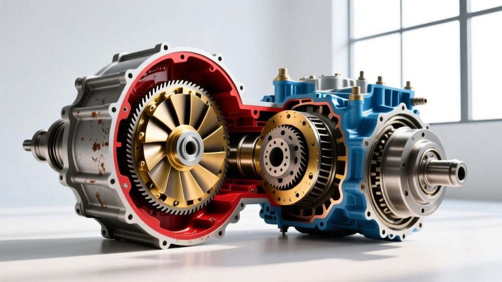
The torque converter serves as the fluid coupling between the engine and the transmission. It is physically bolted to the engine's flexplate and mechanically drives the transmission's front oil pump via a hub-and-gear interface. When the fitment is compromised, the resulting stress vectors are transferred directly into the rotating assembly, generating noise.
The "Three-Click" Seating Rule and Pump Binding
Before the torque converter is ever bolted to the flexplate, it must be fully seated into the transmission bellhousing. A properly seated TC will engage the input shaft, the stator support, and the front pump gear. This is universally known in the industry as the "three-click" rule. According to Sonnax Technical Resources, failing to achieve full seating means the TC cover is pulled forward by the flexplate bolts to bridge the gap. This axial pulling force bows the TC cover inward, causing the pump drive gear to bind against the stator support. The immediate symptom is a high-pitch whining torque converter noise at idle that fluctuates slightly with engine RPM but does not change when the transmission is shifted into gear.
Flexplate Bolt Bottoming and TCC Interference
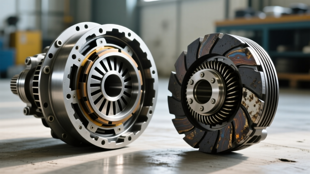
Another pervasive issue involves the physical length of the flexplate-to-TC bolts. The torque converter cover features threaded pads or welded nuts. If the chosen bolts are even 2mm to 3mm too long, they will penetrate through the pad and protrude into the internal cavity of the TC. At idle, these protruding bolt tips strike the internal turbine fins or the Torque Converter Clutch (TCC) apply plate. This produces a metallic rattling or cyclic knocking noise at idle. If left unaddressed, the bolts will eventually puncture the TCC friction material, contaminating the transmission fluid and requiring a $1,800 to $3,000 complete transmission teardown.
Gen 3 vs. Gen 4 LS Flexplate Nuances
One of the most common scenarios generating torque converter noise at idle occurs during GM LS engine swaps. The crankshaft flange thickness varies significantly between engine generations. A Gen 3 (e.g., 5.3L LM7) crank flange is thicker than a Gen 4 (e.g., 6.2L L92) flange by approximately 0.150 inches.
If a builder uses a Gen 3 flat flexplate on a Gen 4 crankshaft without the required spacer, the flexplate sits too far rearward. When the TC is bolted up, it is pulled back, binding the front pump gear and causing an immediate idle whine. Conversely, using a Gen 4 flexplate on a Gen 3 crank without accounting for the thickness pushes the flexplate too far forward, causing the TC pads to strike the flexplate before the bolts can properly thread, resulting in severe knocking at idle. Always measure the crank flange and utilize the correct flat or weighted flexplate (and appropriate 0.400" spacers where mandated) to maintain the factory TC pad-to-flexplane clearance.
Torque Converter Bolt Specifications & Clearances
Precision is non-negotiable. The following table outlines factory specifications for common platforms. Deviating from these torque specs or clearances is a primary catalyst for idle noise and premature component wear. Data compiled from OEM service manuals and ATRA Online Tech Info.
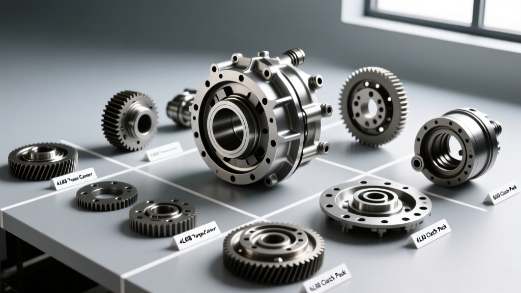
| Transmission Model | Bolt Specification | Torque Spec | Required Flexplate Clearance | Common Failure Noise |
|---|---|---|---|---|
| GM 6L80 / 6L90 | M10 x 1.5 | 37 lb-ft (50 Nm) | 3/16" (4.7mm) | TCC drag rattle, metallic clank |
| Ford 6R80 | M10 x 1.25 | 35 lb-ft (47 Nm) | 1/8" - 3/16" | Pump gear high-pitch whine |
| ZF 8HP70 / 8HP45 | M10 x 1.25 | 33 lb-ft (45 Nm) | 0.08" - 0.12" | Stator whine, idle shudder |
| GM 4L60E / 4L65E | M10 x 1.5 | 35 lb-ft (47 Nm) | 1/8" - 3/16" | Cover distortion knock |
Note on ZF 8HP Platforms: The ZF 8-speed utilizes a highly sensitive stator support tube. Over-torquing the flexplate bolts beyond 35 lb-ft can distort the TC cover enough to misalign the stator tube, causing a distinct shudder and whining noise at idle that is frequently misdiagnosed as a failed mechatronic unit or worn internal clutches.
Step-by-Step Diagnostic & Correction Protocol
If a vehicle exhibits torque converter noise at idle immediately following a powertrain installation or transmission swap, execute this diagnostic protocol before condemning internal components:
- Step 1: Verify Axial Clearance. Before tightening the flexplate bolts, push the TC fully rearward against the flexplate. Measure the gap between the TC mounting pad and the flexplate surface. It must be between 1/8" and 3/16". If it is flush or negative, the TC is not seated, or the wrong flexplate/spacer combination is installed.
- Step 2: Check Bolt Thread Engagement. Thread the bolts into the TC pads without the flexplate in place. Mark the bolt with a paint pen where it sits flush with the pad. Remove the bolt and measure the protrusion. If the bolt extends past the internal ceiling of the pad, it will interfere with the TCC. Machine the bolts down or source OEM-correct fasteners.
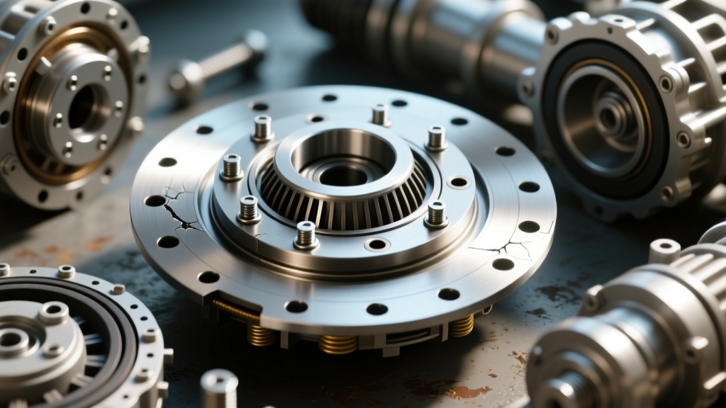
- Step 3: Dial Indicator Runout Test. Mount a magnetic dial indicator to the engine block and rest the probe on the TC cover. Rotate the engine by hand. Runout should not exceed 0.015". Excessive runout indicates a warped TC cover (often caused by using bolts to "pull" the TC to the flexplate) or a bent flexplate, both of which cause cyclic knocking at idle.
- Step 4: Star-Pattern Torque Sequence. Always torque the TC-to-flexplate bolts in a crisscross star pattern in three progressive steps (e.g., 15 lb-ft, 25 lb-ft, final spec). This ensures the clamping load is distributed evenly, preventing the TC cover from warping and binding the internal pump drive.
Conclusion: Precision Over Assumption
Torque converter noise at idle is a symptom that demands a methodical, measurement-based approach. By respecting the three-click seating rule, verifying Gen-specific flexplate thicknesses, and adhering strictly to OEM torque specs and bolt lengths, technicians and builders can eliminate the mechanical binding that causes these acoustic warnings. Never use fasteners to bridge a gap; if the clearance is not correct, the hardware or the seating is wrong. Addressing these fitment nuances on the lift prevents catastrophic pump and TCC failures on the road.