Understanding Electric PTO Clutch Drag on the L120
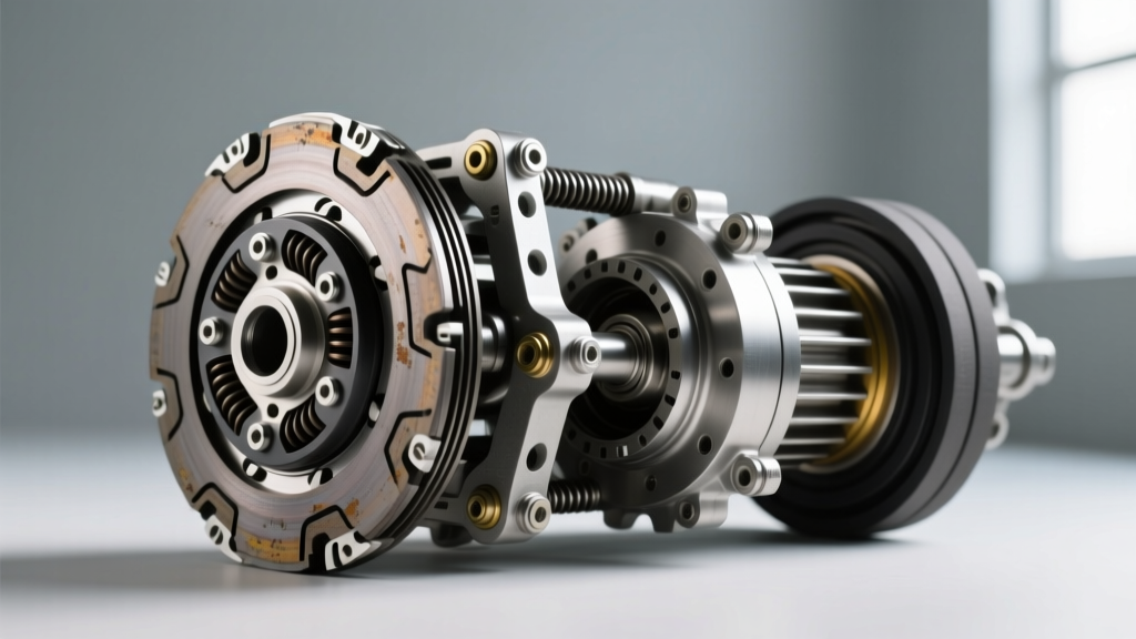
The John Deere L120 lawn tractor is equipped with a 22HP V-twin engine that relies on an electromagnetic Power Take-Off (PTO) clutch to engage and disengage the mower deck blades. Unlike a traditional manual automotive transmission clutch that uses hydraulic or mechanical pedal linkage, the John Deere L120 PTO clutch is an electrically actuated friction device. When you flip the PTO switch, 12 volts energize an electromagnetic coil, pulling the armature plate against the rotor to drive the pulley. When the switch is turned off, the magnetic field collapses, and wave washers or leaf springs pull the armature away to release the blades.
When you experience clutch drag and release problems, the mower blades continue to spin—or exhibit severe resistance—even after the PTO switch is disengaged. This is a critical safety hazard and a sign of mechanical binding, residual magnetism, or electrical ghost voltage. In this comprehensive step-by-step guide, we will diagnose and resolve PTO clutch drag, ensuring your L120 operates safely and efficiently.
Safety First: Lockout and Deck Support
Before performing any drivetrain or PTO diagnostics, you must eliminate the risk of accidental engagement or crushing injuries.
- Disconnect the Battery: Always remove the negative (-) battery cable first to prevent accidental cranking or electrical shorts.
- Secure the Mower Deck: If you need to access the underside of the PTO clutch, support the front of the tractor on jack stands. Never rely solely on a hydraulic jack.
- Wear Cut-Resistant Gloves: The clutch housing and mower blades can have sharp, rusted edges.
Step 1: Rule Out Electrical Ghost Voltage
Before tearing into the mechanical air gap, you must verify that the clutch is actually receiving a full disengagement signal. A failing PTO switch or a sticking relay can allow 'ghost voltage' to leak into the clutch circuit, keeping the electromagnet partially energized.
Testing for Voltage Bleed
- Reconnect the battery temporarily for this test.
- Set your digital multimeter to DC Voltage.
- Probe the two wires at the PTO clutch connector while the ignition is ON but the PTO switch is in the OFF position.
- A reading of 0.0V to 0.2V is normal. If you read 1.0V or higher, the clutch is experiencing partial magnetic engagement due to a faulty PTO switch, a bad safety interlock module, or chafed wiring shorting to a live circuit.
- If ghost voltage is present, replace the PTO switch assembly before proceeding to mechanical adjustments.
Step 2: Inspect and Adjust the Armature Air Gap
If the electrical circuit is clean, the most common cause of John Deere L120 PTO clutch drag is an improperly set air gap. Over time, the friction surfaces wear down, causing the air gap to widen. However, if the clutch was recently replaced or improperly adjusted, the air gap might be too tight. If the gap is less than 0.010 inches, residual magnetism or microscopic surface imperfections can cause the armature to drag against the rotor even when power is cut.
Required Tools and Target Measurements
You will need a set of feeler gauges and a 3/8-inch wrench or socket (depending on the specific adjustment nut size on your clutch model).
| Specification | Target Measurement | Action Required |
|---|---|---|
| Minimum Air Gap | 0.012' (0.30mm) | Loosen adjustment nuts if tighter |
| Optimal Air Gap | 0.015' (0.38mm) | Ideal setting for clean release |
| Maximum Air Gap | 0.022' (0.55mm) | Tighten adjustment nuts; clutch may slip if wider |
Adjustment Procedure
- Locate the three or four adjustment nuts situated around the perimeter of the clutch assembly. These nuts compress the leaf springs that dictate the armature's resting position.
- Insert a 0.015-inch feeler gauge between the armature and the rotor face at each adjustment point.
- Loosen or tighten the adjustment nuts until you feel a slight, uniform drag on the feeler gauge at every point. The gap must be perfectly concentric; a skewed armature will cause one side to release while the other side drags.
- Manually rotate the clutch pulley by hand. It should spin freely with only the slight resistance of the internal bearings. If you hear a metallic scraping sound, the gap is too tight or the rotor is warped.
Step 3: Addressing Friction Surface Rust and Glazing
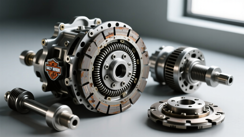
The L120 is frequently stored in unclimate-controlled sheds, exposing the PTO clutch to high humidity. When the tractor sits for weeks, flash rust forms on the cast-iron friction surfaces. When you engage the PTO, the clutch slips slightly, generating immense heat. This heat bakes the rust and grass debris into a hardened, glass-like glaze. This glaze creates severe 'stiction'—meaning the surfaces physically stick together and fail to release when the magnetic field drops.
The Burnishing and Cleaning Protocol
According to Warner Electric PTO Clutches, a leading OEM manufacturer of agricultural electromagnetic clutches, periodic burnishing is required to maintain proper friction coefficients and release characteristics.
- Remove the clutch assembly from the crankshaft if heavy rust is visible. (Note the center bolt torque spec: 75-85 ft-lbs with medium threadlocker).
- Use a non-abrasive Scotch-Brite pad and acetone to aggressively scrub both the rotor and armature friction faces. Never use sandpaper or a wire wheel, as this will gouge the precision-machined surfaces and create localized hot spots.
- Wipe the surfaces completely clean with a lint-free cloth.
- Reinstall the clutch and perform a 'burn-in' procedure: Engage the PTO at half-throttle for 5 seconds, then disengage. Repeat this 10 to 15 times. This micro-slipping process mates the surfaces and clears out microscopic debris, restoring a clean, dry release.
Step 4: Checking Rotor Bearings and Return Springs
If the air gap is correct, the electrical system is sound, and the surfaces are clean, the drag is likely originating from internal mechanical failure.
Bearing Seizure
The PTO clutch contains a sealed internal ball bearing that supports the armature hub on the crankshaft. If the seal fails, moisture enters the bearing race. A corroded bearing will bind, preventing the armature from snapping back to its resting position. Grab the pulley and attempt to wobble it radially and axially. Any gritty feeling, notchiness, or lateral play indicates a blown bearing. PTO clutch bearings are generally not serviceable; the entire assembly must be replaced.
Fatigued Return Springs
Electromagnetic clutches rely on wave washers or stamped leaf springs to physically push the armature away from the rotor when power is cut. Over thousands of engagement cycles, these springs suffer from metal fatigue and lose their tensile strength. If the springs are weak, they cannot overcome the residual magnetism of the coil core, resulting in a delayed release or continuous drag. Visual inspection for cracked or flattened wave washers is mandatory during a rebuild.
When to Replace the PTO Clutch Assembly
While adjustments and cleaning can solve minor drag issues, severe thermal damage requires a full replacement. If the clutch has been dragging for an extended period, the friction surfaces will exhibit deep blue or purple heat-stress marks (bluing). Once the metallurgical structure of the cast iron is altered by extreme heat, the clutch will never release cleanly again.
When sourcing a replacement, you have two primary routes. Referencing the John Deere Parts & Service catalog, here is a comparison of your options:
| Clutch Type | Part Number Example | Estimated Cost (2026) | Pros & Cons |
|---|---|---|---|
| OEM John Deere | AM130365 | $190 - $240 | Exact fitment, OE wiring harness, 12-month warranty. Higher cost. |
| Premium Aftermarket | Stens 255-865 / Xtreme | $95 - $130 | High torque capacity, often features upgraded epoxy-sealed coils. May require minor wiring splicing. |
| Budget Aftermarket | Generic Rotary / Import | $60 - $85 | Cheap upfront, but prone to premature bearing failure and inconsistent air gaps. |
Expert Torque Spec Reminder: When installing the new PTO clutch onto the L120's 1-inch crankshaft, apply a single drop of blue Loctite (Threadlocker 242) to the center mounting bolt. Torque the bolt to 80 ft-lbs (108 Nm). Failure to use threadlocker will result in the bolt backing out due to the harmonic vibrations of the V-twin engine, which can destroy the crankshaft keyway.
Summary Checklist for PTO Drag Diagnostics
- Verify 0.0V ghost voltage at the connector with the PTO switch OFF.
- Measure the air gap; adjust to exactly 0.015 inches using a feeler gauge.
- Clean friction surfaces with acetone and Scotch-Brite to remove stiction-causing rust.
- Perform a 15-cycle burn-in procedure to mate the friction materials.
- Inspect the internal bearing for notchiness and check wave washers for fatigue.
- Replace the assembly if deep thermal bluing is present on the rotor face.
By following this systematic diagnostic approach, you can eliminate the dangerous John Deere L120 PTO clutch drag and release problems, ensuring that your mower deck stops spinning the moment you disengage the switch. Regular end-of-season maintenance, including blowing out grass clippings from the clutch housing and applying a light dielectric grease to the electrical connector, will drastically extend the life of your electromagnetic drivetrain components.