The Core Issue: Why Your Performance Upgrade is Misbehaving
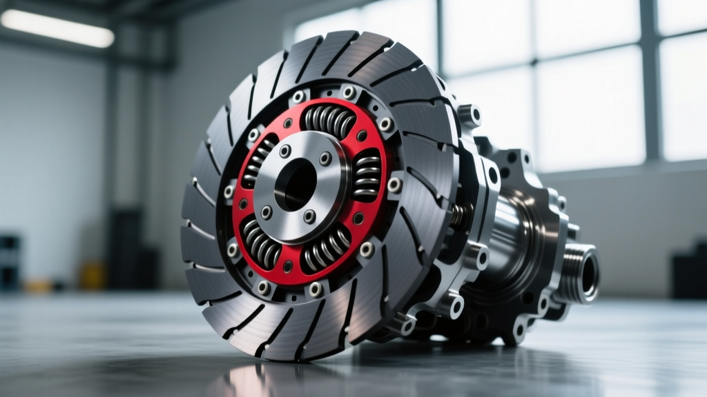
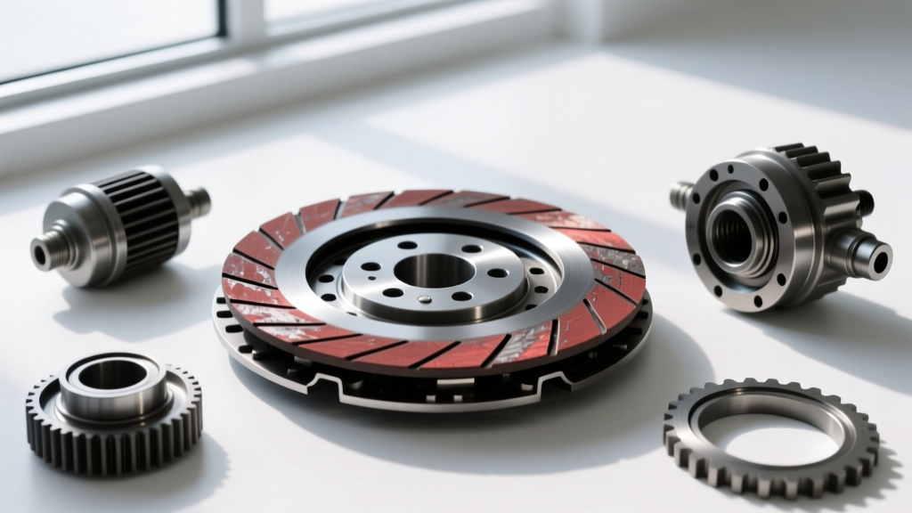
When enthusiasts install a comprehensive EPI performance clutch kit—or comparable high-clamp-load aftermarket assemblies—they often encounter unexpected drivetrain symptoms. As of 2026, with aftermarket twin-turbo kits for platforms like the Gen V LT4, Ford Godzilla, and Nissan VR38DETT pushing well past 900 lb-ft of torque, the margin for error in friction material selection and installation is zero. A high-performance clutch is not a simple bolt-on upgrade; it is a calibrated friction management system. If you are experiencing low-speed chatter, high-RPM slip, or gear drag, the issue rarely lies in a single defective part. Instead, it is usually a mismatch between your chosen performance clutch disc options and the supporting drivetrain hardware.
Diagnosing these symptoms requires a methodical approach. Before tearing the transmission back out, you must isolate whether the failure is rooted in the friction material's coefficient of friction (µ), the flywheel mating surface, hydraulic over-extension, or bellhousing misalignment. Below is a symptom-based diagnostic matrix to help you troubleshoot your setup.
Diagnostic Matrix: Symptom vs. Friction Material
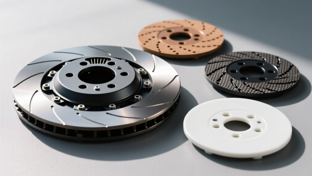
Different friction materials react uniquely to heat, moisture, and clamping force. Use this matrix to identify the likely culprit based on your primary complaint.
| Friction Material | Coefficient (µ) | Max Temp (°F) | Break-in Requirement | Common Failure Symptom |
|---|---|---|---|---|
| Organic (Standard) | 0.30 - 0.35 | 400°F | Minimal (50 miles) | High-RPM slip, fading under load |
| Kevlar / Aramid | 0.35 - 0.40 | 600°F | Strict (500+ miles stop-and-go) | Glazing, low-speed slip if improperly bedded |
| Ceramic (Puck/Full) | 0.45 - 0.55 | 800°F+ | Moderate (5-10 hard slips) | Severe low-speed chatter, drivetrain shock |
| Sintered Iron | 0.55 - 0.65 | 1000°F+ | Aggressive (Track use only) | Extreme chatter, input shaft shearing |
Deep Dive: Troubleshooting Specific Disc Materials
Ceramic and Sintered Iron: The Chatter Culprits
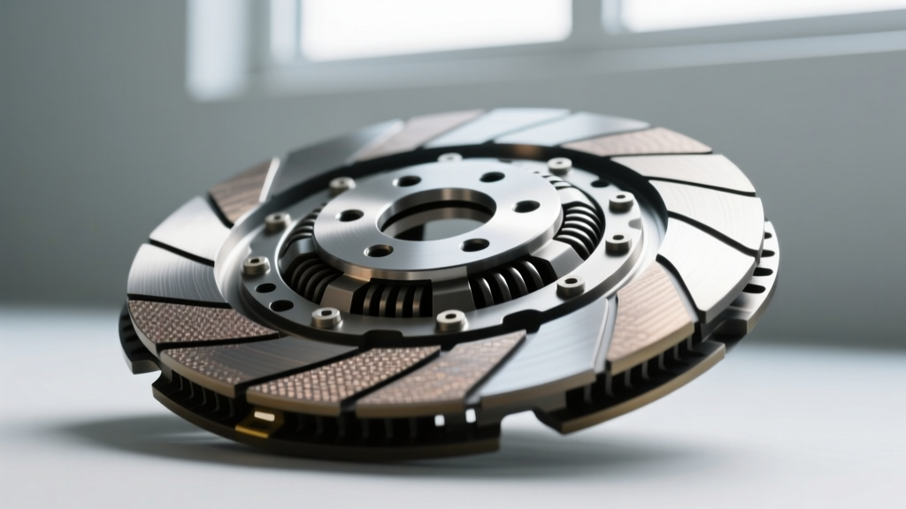
If your EPI performance clutch kit utilizes a ceramic puck or sintered iron disc, low-speed chatter is almost a guaranteed characteristic, not necessarily a defect. These materials lack the "marcel" (wave) springs found in organic discs, meaning there is zero progressive engagement. The friction surface bites instantly.
Troubleshooting Chatter: If the chatter is violent enough to shake the chassis, check the flywheel step height. For a pull-type clutch, the step height must typically be between 0.010" and 0.020". For a push-type, it is generally 0.400" to 0.500". If the machine shop resurfaced the flywheel flat without cutting the step, the pressure plate fingers will over-extend, altering the diaphragm spring geometry and causing violent engagement. Additionally, inspect your engine and transmission mounts; degraded polyurethane or broken hydraulic mounts will amplify the natural harmonics of a ceramic disc into severe chassis chatter.
Kevlar and Carbon-Kevlar: The Glazing Trap
Kevlar is renowned for its high burst strength and smooth engagement, making it a favorite for high-horsepower street/strip builds. However, Kevlar requires a meticulous break-in procedure. If a driver immediately subjects a new Kevlar disc to highway pulls or drag-strip launches, the surface will overheat and glaze. Once glazed, the µ drops drastically, resulting in high-RPM slip even with a 3,000 lb clamp load pressure plate.
Troubleshooting Slip: If a Kevlar disc is slipping, pull the transmission and inspect the disc. If the friction material appears shiny and hardened, it is glazed. In mild cases, you can scuff the surface with 80-grit sandpaper and re-bed it. In severe cases, the heat has compromised the resin binders, and the disc must be replaced. Always mandate 500 miles of varied, stop-and-go city driving to properly transfer the Kevlar material to the flywheel and pressure plate surfaces.
The Flywheel and Hydraulics Variable
A performance clutch disc can only perform as well as the surfaces clamping it and the system releasing it. Two critical areas often overlooked during an EPI performance clutch kit installation are flywheel runout and hydraulic throwout bearing (HTOB) setup.
Flywheel Runout and Concentricity
According to McLeod Racing Technical Resources, flywheel face runout must not exceed 0.005" Total Indicator Runout (TIR). If the flywheel is warped or the crankshaft flange has excessive end-play, the clutch disc will wobble during engagement. This wobble forces the hydraulic system to rapidly pulse, which the driver feels as a rhythmic shudder or chatter through the pedal. Always use a dial indicator mounted to the engine block to verify flywheel runout before installing the clutch assembly.
Hydraulic Throwout Bearing (HTOB) Air Gap
Modern performance setups frequently utilize internal HTOBs. A fatal installation error is pre-loading the HTOB against the pressure plate fingers. As the engine reaches high RPM (e.g., 6,500+ RPM), centrifugal force causes the diaphragm fingers to bow outward. If there is no air gap, the fingers will push against the HTOB, slightly releasing the clutch and causing catastrophic high-RPM slip.
The Fix: You must maintain an air gap of 0.100" to 0.150" between the HTOB bearing face and the pressure plate fingers when the clutch is fully engaged. Use HTOB shims or adjustable master cylinder pushrods to dial in this exact clearance.
Bellhousing Alignment: The Silent Disc Killer
If your performance clutch disc is wearing unevenly, or if you experience gear drag and difficulty shifting into first or reverse, bellhousing misalignment is the likely cause. As detailed by Tremec Drivetrain Solutions, the transmission input shaft must be perfectly concentric with the engine crankshaft. If the bellhousing is offset, the input shaft binds inside the disc hub, preventing the disc from fully releasing when the pedal is depressed.
Diagnostic Procedure:
- Mount a dial indicator to the crankshaft flange or flywheel.
- Sweep the inside bore of the bellhousing.
- Calculate the TIR. The maximum allowable offset for high-performance applications is 0.005".
- If the TIR exceeds 0.005", install adjustable offset dowel pins (available in 0.007", 0.014", and 0.021" offsets) to center the bellhousing perfectly.
Installation Torque & Clearance Specifications
Proper clamping force starts at the bolt head. Using an impact wrench to install flywheel or pressure plate bolts will result in uneven clamp loads, leading to warped pressure plates and localized disc slippage. Always use a calibrated torque wrench and follow the OEM or fastener manufacturer's sequence.
Critical Torque Specifications (OEM / ARP Equivalents):
- GM LS/LT (Flywheel to Crank): 74 lb-ft (Use ARP thread lubricant, not engine oil, if using aftermarket bolts).
- Ford Coyote 5.0L (Flywheel to Crank): 59 lb-ft (Verify specific year, some require torque-to-yield).
- Chrysler Gen III Hemi (Flywheel to Crank): 70 lb-ft.
- Pressure Plate to Flywheel (Typical 10.5" - 12"): 25 to 35 lb-ft in a star pattern, incrementally increasing by 10 lb-ft per pass to ensure even diaphragm seating.
Expert Insight: When upgrading to a multi-disc or high-clamp-load single disc setup, the stock master cylinder bore size is often insufficient to fully stroke the heavier diaphragm spring. If your pedal feels like it is hitting a brick wall and the clutch won't fully disengage, upgrading from a 3/4" to a 13/16" or 7/8" master cylinder bore will increase hydraulic volume, ensuring complete release without altering the pedal ratio.
For further reading on friction material dynamics and break-in procedures, refer to the SPEC Clutch Technical Information database. Ultimately, diagnosing a failing or misbehaving EPI performance clutch kit requires looking beyond the disc itself. By verifying flywheel geometry, hydraulic clearances, and bellhousing concentricity, you can extract the full, reliable torque-holding potential of your chosen friction material.