Understanding the journey from engine combustion to the wheels requires mastering the fluid coupling that makes automatic transmissions possible. Without it, every stop at a red light would require you to manually disengage the engine from the drivetrain.
If you have ever wondered how an automatic transmission allows a vehicle to come to a complete stop while the engine continues to idle, the answer lies inside the bell housing. The transition from engine horsepower to torque converter input is one of the most elegant examples of hydrodynamic engineering in the automotive world. For beginners and seasoned gearheads alike, grasping how this component multiplies force, manages heat, and eventually locks up for highway efficiency is essential for both diagnostics and performance building.
The Core Concept: Engine Horsepower to Torque Converter Transfer
An internal combustion engine produces rotational force (torque) and work over time (horsepower). However, an engine cannot drop below its minimum idle speed without stalling. If the engine were hard-coupled to the transmission input shaft via a solid mechanical clutch, the vehicle would lurch forward violently or the engine would die the moment the brakes were applied.
The torque converter solves this by acting as a fluid coupling. It takes the mechanical horsepower generated by the engine's crankshaft and converts it into hydrodynamic energy. This fluid energy is then transferred back into mechanical torque to drive the transmission's input shaft. This slip allows the engine to maintain its idle RPM while the vehicle remains stationary, and it provides a smooth, seamless multiplication of torque when you step on the accelerator from a dead stop.
Inside the Shell: The Three Main Components
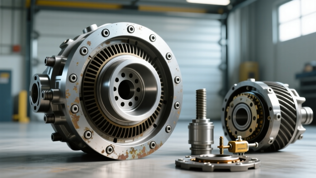
To understand the physics, you must look inside the welded steel shell of the converter. According to HowStuffWorks, a standard torque converter relies on three primary internal elements bathed in automatic transmission fluid (ATF):
- The Impeller (Pump): Bolted directly to the converter housing, which is bolted to the engine's flexplate. As the engine spins, the impeller spins, using centrifugal force to fling ATF outward and into the turbine.
- The Turbine: Connected to the transmission input shaft. The fluid striking the turbine's blades causes it to spin, effectively transferring the engine's power into the gearbox.
- The Stator: The unsung hero of torque multiplication. Mounted on a one-way clutch in the center, the stator catches the fluid exiting the turbine and redirects it back into the impeller. This redirection prevents the fluid from fighting the impeller's rotation, effectively multiplying the torque output.
The Three Stages of Operation
The relationship between horsepower and torque converter behavior changes depending on the driving scenario. The converter operates in three distinct phases:
1. Stall Phase (Idle)
When the vehicle is in gear but the brakes are applied, the turbine is held stationary while the impeller spins at engine idle speed (usually 600-800 RPM). The torque converter generates minimal heat and transfers very little torque. The RPM at which the engine maxes out against a stationary turbine at wide-open throttle is known as the "stall speed."
2. Acceleration Phase (Torque Multiplication)
When you release the brake and apply throttle, the impeller spins much faster than the turbine. The stator remains locked by its one-way clutch, redirecting fluid to assist the impeller. During this phase, the converter can multiply engine torque by a ratio of up to 2.5:1. This is why an automatic vehicle can launch so smoothly and forcefully from a stop.
3. Coupling Phase (Cruising)
As the vehicle reaches cruising speed, the turbine catches up to the impeller (usually spinning at about 90% of the impeller's speed). At this point, fluid strikes the back of the stator blades, causing the one-way clutch to release. The stator freewheels, and the converter acts as a simple fluid coupling. Torque multiplication ceases, and the converter operates at roughly a 1:1 ratio, minus a small amount of parasitic slippage.
OEM Torque Converter Specifications & Applications
Different transmissions require vastly different converter designs to handle varying levels of horsepower and torque. Below is a comparison of common setups found in modern and legacy vehicles:
| Transmission Model | Common Application | Converter Diameter | Typical Stall Speed | OEM Replacement Cost |
|---|---|---|---|---|
| GM 4L60E | 1993-2013 GM V8 Trucks/Cars | 298mm (11.7") | 1500 - 1800 RPM | $150 - $250 (Reman) |
| GM 6L80 | 2006-2020 GM Trucks/Camaro | 300mm (11.8") | 1800 - 2100 RPM | $350 - $500 (OEM) |
| ZF 8HP70 | 2012+ Chrysler/BMW/Jaguar | 260mm (w/ Damper) | 1600 - 1900 RPM | $800 - $1,200 (OEM) |
The Magic of the Torque Converter Clutch (TCC)
While fluid coupling is great for stop-and-go traffic, the 5% to 10% slippage inherent in the coupling phase wastes horsepower and generates excessive heat. To solve this, engineers introduced the Torque Converter Clutch (TCC).
When the vehicle reaches a specific speed and gear (usually 3rd or 4th gear), the transmission control module (TCM) commands a solenoid to apply hydraulic pressure—often between 110 and 140 PSI—against a friction-lined piston inside the converter. This piston presses against the front cover, mechanically locking the turbine to the impeller. The result is a 1:1 direct mechanical connection, eliminating slippage, reducing ATF temperatures, and improving fuel economy.
In modern 2026 vehicles, TCC strategy has evolved. Instead of a harsh, on-off lockup, modern transmissions utilize "controlled micro-slip." The TCM modulates the TCC apply valve to allow a microscopic amount of slip (10-30 RPM) to absorb engine harmonics and prevent drivetrain shudder, a topic heavily researched by Sonnax engineering teams.
Installation Realities: Torque Specs and Fluid
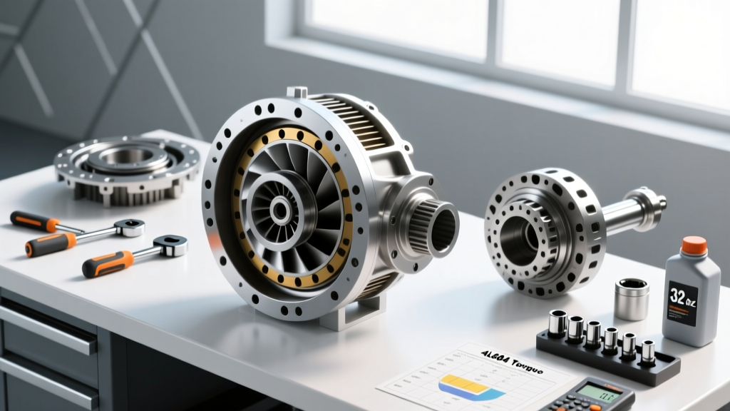
If you are replacing a torque converter, precision is mandatory. A misaligned converter will destroy the transmission oil pump upon startup. When installing a converter onto a GM Gen III/IV LS V8 flexplate, ensure the converter is fully seated into the transmission oil pump gear (you should feel three distinct "clunks" or drops as it passes the stator support, pump gear, and turbine hub).
- Flexplate to Crankshaft Bolts: Typically 74 lb-ft (for standard GM LS applications).
- Converter to Flexplate Nuts: Typically 35 to 45 lb-ft. Always use thread locker.
- Pre-Fill Requirement: Never install a dry converter. A standard 298mm 4L60E converter holds roughly 4 to 5 quarts of Dexron VI ATF. Always pre-fill through the hub before mating it to the engine to prevent instant pump cavitation and dry-start wear.
Diagnosing Torque Converter Symptoms
Because the torque converter is a sealed, welded unit, internal failures manifest as distinct drivability symptoms. Recognizing these early can save you from a complete transmission rebuild.
- TCC Shudder (P0741 / P1870): Feels like driving over rumble strips at 45-55 MPH. This is caused by degraded ATF losing its friction modifiers, or a failing TCC apply valve in the valve body (often fixed with a Sonnax 77754-01K TCC apply valve kit).
- Overheating ATF: If the stator's one-way clutch fails and locks up in the freewheel direction, the converter will multiply torque even at highway speeds, generating massive heat (often exceeding 240°F) and boiling the transmission fluid.
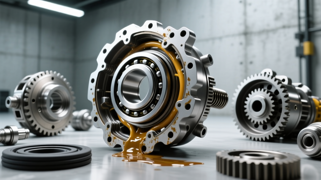
- Contaminated Fluid (The "Glitter" Bomb): If the internal needle bearings or thrust washers fail, metallic debris will circulate through the cooler lines and into the transmission valve body, requiring a complete flush and likely a rebuild.
- Loss of Acceleration (Slipping): If the internal fins are damaged or the fluid level is critically low, the impeller cannot transfer horsepower to the turbine, resulting in a sensation similar to a slipping clutch in a manual car.
For more in-depth diagnostic procedures and tear-down analysis, the Automatic Transmission Rebuilders Association (ATRA) provides extensive technical bulletins on hydrodynamic failure points.
Summary
The transfer of engine horsepower to torque converter output is a masterclass in fluid dynamics. By understanding the roles of the impeller, turbine, and stator, as well as the critical function of the TCC, you can better diagnose drivability issues, select the right stall speed for performance builds, and appreciate the engineering that keeps modern automatic transmissions shifting smoothly for hundreds of thousands of miles.