The Evolution of Active Axles: Why Standard Service Falls Short
In the modern era of high-performance and heavy-duty drivetrains, the traditional open or purely mechanical limited-slip differential has been largely superseded by the electronic Limited-Slip Differential (eLSD). Platforms utilizing BorgWarner or Dana torque-vectoring axles rely on internal hydraulic pumps, PWM-controlled solenoids, and multi-plate clutch packs to distribute torque across the rear wheels in milliseconds. While the fundamental gearset still requires standard ring and pinion lubrication, the hydraulic control circuit demands a vastly different maintenance protocol.
When you perform a fluid change on an active differential, you are not just swapping gear oil; you are altering the hydraulic viscosity and friction coefficients of the clutch pack environment. Consequently, a standard drain-and-fill is incomplete. To ensure the clutch clamps correctly without shuddering or slipping, a differential pressure transmitter calibration must be performed via a bidirectional OBD-II scan tool. This guide details the exact step-by-step procedure, fluid intervals, and calibration protocols required for modern eLSD systems as we navigate the complex drivetrain architectures of 2026.
Service Intervals and Fluid Specifications
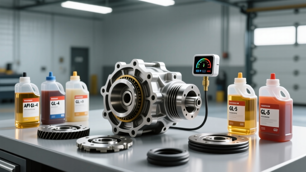
Unlike passive differententials that can often run 100,000 miles on a single fill, the internal hydraulic pumps and clutch friction materials in an eLSD degrade the fluid's shear stability and friction modifiers much faster. Below is the definitive maintenance matrix for common active differential platforms.
| Platform / Axle Type | Fluid Specification | Friction Modifier | Capacity | Service Interval |
|---|---|---|---|---|
| GM Alpha 8.6' eLSD (Camaro/CT4-V) | Dexron ULV or 75W-85 GL-5 | GM AFE (Anti-Friction Enhancer) | 1.6 Liters | 45,000 miles / 72,000 km |
| Ford 8.8 IRS eLSD (Mustang Perf. Pack) | Motorcraft 75W-85 Synthetic | XL-3 Friction Modifier (4 oz) | 1.5 Liters | 50,000 miles / 80,000 km |
| BorgWarner Torque Vectoring (Porsche/Audi) | OEM Specific TF-0870 | Pre-mixed (Do not add) | 1.2 Liters | 40,000 miles / 60,000 km |
Note: Always consult the specific OEM service manual. Using standard 75W-90 GL-5 gear oil in an eLSD without the correct friction modifier will cause immediate clutch chatter and trigger hydraulic pressure fault codes.
Step 1: Preparation and Safe Lifting
Proper fluid level verification requires the vehicle to be perfectly level. Because eLSDs feature internal hydraulic reservoirs and external cooling lines on some heavy-duty truck applications, a four-post lift or a perfectly level floor with jack stands is mandatory.
- Tools Required: 3/8' drive hex sockets (typically 8mm or 10mm for fill/drain plugs), fluid transfer pump, catch pan, OEM scan tool (e.g., Snap-on Zeus+, Autel MaxiSys, or GM GDS2/Ford FDRS).
- Safety: Chock the front wheels. Ensure the parking brake is released so the rear axles can rotate freely during the bleeding and calibration phases.
Step 2: Draining and Flushing the eLSD Sump
- Warm the Fluid: Drive the vehicle for 10-15 minutes to bring the differential fluid to operating temperature (approx. 140°F / 60°C). This suspends metallic particulates in the oil for complete evacuation.
- Remove Fill Plug First: Always break the fill plug loose before the drain plug to prevent a scenario where the differential drains but the fill plug is seized.
- Drain the Sump: Remove the drain plug (Torque spec for removal is typically 33 Nm / 24 lb-ft, but break torque may be higher). Allow the fluid to drain completely for at least 20 minutes.
- Inspect for Clutch Debris: eLSDs naturally shed friction material. A fine gray paste on the magnetic drain plug is normal. However, if you find metallic flakes or large clutch lining chunks, the internal hydraulic pump or clutch pack requires a teardown.
Step 3: Refilling and Preliminary Hydraulic Bleeding
- Reinstall Drain Plug: Apply a fresh crush washer or specified thread sealant. Torque to 33 Nm (24 lb-ft).
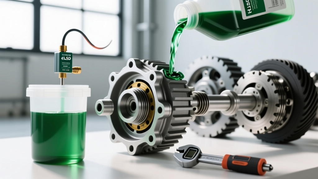
- Inject Fluid: Using a fluid transfer pump, inject the specified gear oil and friction modifier into the fill hole until it begins to weep out.
- Prime the Hydraulic Pump: This is where eLSD service diverges from standard axles. The internal hydraulic pump must be primed to prevent cavitation, which will destroy the pump gears and skew the pressure sensor readings. Connect your bidirectional scan tool, navigate to the Chassis > Drivetrain > eLSD Control Module, and command the 'Hydraulic Pump Prime' routine. This runs the pump at 30% duty cycle for 15 seconds to pull fluid into the accumulator and clutch feed galleries.
- Top Off and Seal: Recheck the fluid level, as the pump priming will draw fluid out of the main sump. Top off until it weeps, then install and torque the fill plug to 33 Nm (24 lb-ft).
Step 4: Differential Pressure Transmitter Calibration
This is the most critical step in the modern differential fluid change procedure. The eLSD utilizes a differential pressure transmitter (often referred to in OEM wiring diagrams as a Line Pressure Sensor or Clutch Pressure Transducer) to measure the hydraulic pressure delta between the pump output and the sump return. This sensor tells the Drivetrain Control Module exactly how much clamping force is being applied to the clutch pack.
When you introduce new fluid, the viscosity, aeration levels, and friction coefficients change. If the module relies on its old adaptive memory, it may over-pressurize or under-pressurize the clutch pack, leading to harsh engagements or slip faults. Performing a differential pressure transmitter calibration resets the zero-point and max-pressure thresholds.
Calibration Procedure via Scan Tool:
- Navigate to the eLSD or Chassis Control Module in your scan tool.
- Select Special Functions or Adaptations.
- Select Differential Pressure Transmitter Calibration (or 'Clutch Pressure Sensor Zero-Point Learn').
- The tool will prompt you to ensure the vehicle is in Park (or Neutral with brakes held for manual applications) and the engine is running to maintain stable system voltage (minimum 12.5V).
- Command the calibration. The scan tool will command the PWM solenoid to fully closed, read the baseline sump pressure to establish the '0 PSI' offset, and then briefly spike the pump to verify the upper limit of the transmitter.
- Once the tool reports 'Calibration Complete', clear any historical adaptive learning values and reset the differential fluid life monitor.
Step 5: Dynamic Road Testing and Clutch Burnish
Following the differential pressure transmitter calibration, the clutch pack must be burnished to mate the new friction modifier with the clutch plates.
- Phase 1 (Low Speed): Drive in a large, empty parking lot. Perform 10 tight, low-speed (10 mph) figure-eights. This forces the eLSD to slip the clutches gently, distributing the friction modifier evenly across the plates.
- Phase 2 (Medium Speed): On a safe, curving road, perform 5-10 moderate acceleration runs through sweeping corners (approx. 35-45 mph). This allows the module to adapt its torque-transfer maps based on the newly calibrated pressure transmitter data.
- Verification: Connect the scan tool and monitor the 'eLSD Clutch Slip Speed' and 'Actual vs. Desired Pressure' PIDs. The actual pressure should track the desired pressure within +/- 5 PSI during cornering loads.
Common Diagnostic Trouble Codes (DTCs) Post-Service
If the calibration is skipped or the wrong fluid viscosity is used, you may encounter the following codes:
- C0407 / C0408: Differential Clutch Control Circuit / Performance. Usually indicates the pressure transmitter is reading values outside the expected range due to incorrect fluid viscosity or air in the hydraulic gallery.
- C0552: Differential Pressure Sensor Calibration Not Learned. A direct flag indicating the zero-point learn was not executed.
Conclusion: Precision is Non-Negotiable
As we look at the 2026 landscape of performance EVs and advanced PHEVs, thermal management and hydraulic precision in the axle assemblies are paramount. The days of simply popping a plug and pumping in generic 80W-90 are over. By adhering to strict fluid specifications, utilizing OEM friction modifiers, and religiously performing the differential pressure transmitter calibration, you ensure the torque-vectoring system operates exactly as the engineers intended—providing seamless grip, predictable handling, and maximum drivetrain longevity.
For further reading on advanced axle technologies and fluid specifications, refer to the BorgWarner eLSD Technical Documentation and the Ford Motorcraft Fluid Specifications Guide.