Understanding the Thermal Dynamics of the 48RE
The 48RE automatic transmission, primarily paired with the 5.9L Cummins turbodiesel in 2003-2007 Dodge Ram 2500 and 3500 trucks, is a legendary heavy-duty workhorse. However, its thermal management is notoriously challenged when subjected to modern towing demands. The 48RE generates immense internal heat due to its high line pressures (often exceeding 225 psi in third and fourth gears under load) and the torque converter slip inherent in its four-speed design. When you add the radiant heat from the Cummins exhaust manifold and turbocharger downpipe, the transmission cooler circuit becomes the single most critical factor in preventing fluid degradation and clutch pack failure.
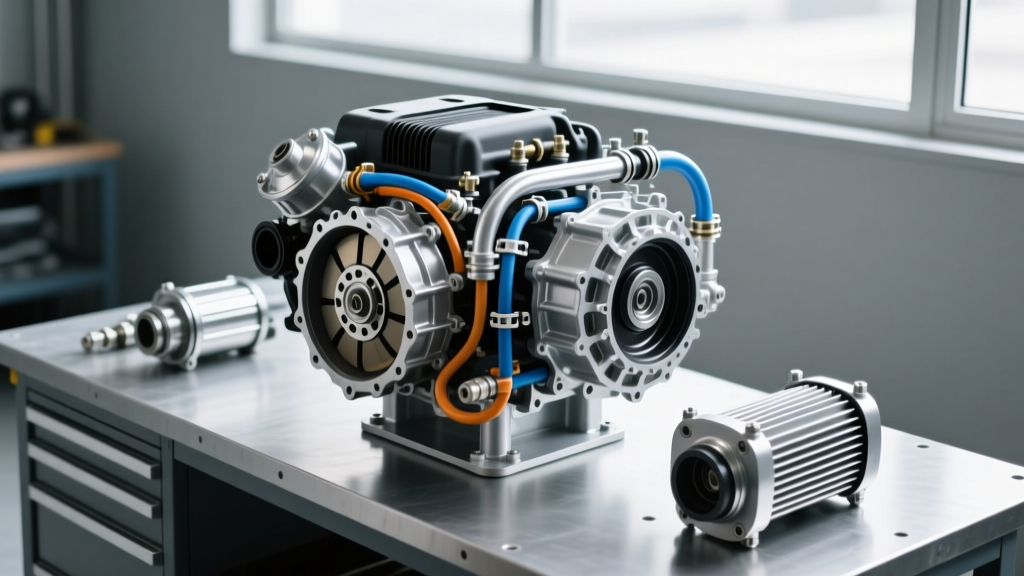
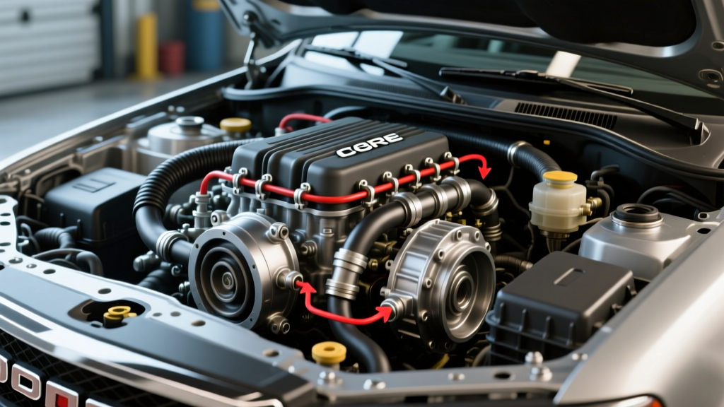
Referencing an accurate 48RE transmission cooler lines diagram is not just about connecting point A to point B; it is about optimizing fluid velocity, minimizing pressure drop, and ensuring the fluid returns to the transmission sump at an optimal temperature. In this comprehensive guide, we break down the exact routing protocols, fitting specifications, and upgrade paths that professional diesel technicians use to keep the 48RE alive under extreme Gross Combined Weight Ratings (GCWR).
Decoding the Flow Path: Auxiliary vs. Radiator Integration
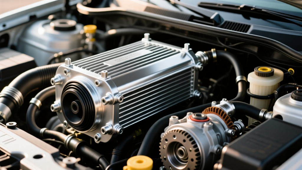
One of the most hotly debated topics in the Cummins community is the correct sequence of the cooling circuit. When you trace the factory 48RE transmission cooler lines diagram, the OEM routing typically sends fluid from the transmission to the radiator's internal heat exchanger first, and then to the auxiliary air-to-oil cooler mounted in front of the A/C condenser. While this works for stock, unloaded driving, it is fundamentally flawed for heavy towing.
The Expert Routing Standard: Aux-First Configuration
For any 48RE pushing over 400 rear-wheel horsepower or towing in excess of 10,000 lbs, we mandate an 'Auxiliary-First' routing configuration. Here is why:
- Maximum Delta-T Cooling: The hottest fluid exiting the transmission (often 220°F to 260°F under load) should hit the largest, most efficient heat exchanger first—the front-mounted auxiliary stacked-plate cooler. This utilizes the maximum temperature differential between the fluid and the ambient air.
- Thermostatic Regulation: After the fluid is aggressively cooled by the auxiliary unit, it routes through the radiator's internal transmission cooler. The engine coolant in the radiator acts as a thermal buffer, bringing the fluid back up to an optimal operating temperature (around 160°F - 180°F) before it re-enters the transmission. This prevents the fluid from running too cold in winter, which causes sluggish valve body shifts and poor torque converter lockup.
Line Sizing, Fittings, and Torque Specifications
A major failure point in DIY cooler installations is the improper mating of cooler lines to the 48RE transmission case and the auxiliary cooler. The 48RE case utilizes specific flare and quick-disconnect fittings that require precise torque to avoid stripping the aluminum case or crushing the steel line flare.
| Component / Location | OEM Line Size | Thread / Fitting Type | Torque Specification | Upgrade Equivalent |
|---|---|---|---|---|
| Transmission Out (Pressure) | 1/2 inch OD Steel | 1/2'-20 UNF Flare Nut | 15 - 18 ft-lbs | -8 AN Male Flare Adapter |
| Transmission In (Return) | 5/8 inch OD Steel | 5/8'-18 UNF Flare Nut | 18 - 22 ft-lbs | -10 AN Male Flare Adapter |
| Radiator Cooler Ports | 1/2 inch OD Steel | Quick-Disconnect / Flare | N/A (Clip) / 15 ft-lbs | Quick-Disconnect to -8 AN |
| Auxiliary Cooler Ports | Varies by Brand | Typically -6 or -8 AN | Hand + 1/4 Turn | -8 or -10 AN Swivel Hose Ends |
Note: Always use a calibrated inch-pound or low-range foot-pound torque wrench when installing adapter fittings into the 48RE aluminum case. Over-torquing will crack the case, resulting in a catastrophic fluid leak and a $3,000+ transmission replacement.
Physical Routing: Clearances, Bending, and Heat Shielding
The physical path of the cooler lines is where many aftermarket kits fail. The 48RE sits directly beneath the Cummins turbocharger and exhaust downpipe. Radiant heat in this zone can easily exceed 400°F, which will rapidly bake standard rubber transmission hoses, causing internal delamination. This delamination creates a hidden restriction that starves the transmission of lubrication and cooling.
Expert Routing Best Practices
- The 3-Inch Exhaust Rule: Never route transmission cooler lines within 3 inches of the exhaust downpipe or DPF (if swapped to a newer configuration). If physical space constraints force a tighter clearance, you must wrap the lines in high-silicone fiberglass fire sleeve (rated to 1,200°F) and apply reflective aluminized heat shielding tape to the side facing the exhaust.
- Bend Radius Limits: When bending OEM steel lines or hard tubing, maintain a minimum bend radius of 2.5 inches. Kinked lines create localized turbulence and pressure drops. Use a professional tubing bender; never use a makeshift pipe bender or pliers, which will flatten the cross-section of the tube and restrict flow.
- Adel Clamp Spacing: Secure the lines to the frame rails using rubber-cushioned Adel clamps (P-clips). Space these clamps no more than 14 inches apart to prevent harmonic vibration from the diesel engine from fatiguing the steel lines at the flare nuts. Never use zip-ties or bare metal hose clamps directly on steel or braided lines.
The 2026 Upgrade Standard: PTFE Braided Lines
In the current 2026 aftermarket landscape, the gold standard for 48RE cooler line routing is the complete elimination of OEM rubber hoses and steel hard lines in favor of PTFE (Polytetrafluoroethylene) lined, stainless steel braided hoses. Brands like SunCoast Diesel and BD Diesel Performance offer comprehensive -8 AN and -10 AN conversion kits specifically designed for the 48RE.
Why make the switch? Standard rubber hoses expand under the 48RE's high line pressure, absorbing hydraulic energy that should be moving fluid through the cooler. PTFE-lined hoses exhibit zero volumetric expansion under 500+ psi. Furthermore, the smooth PTFE interior reduces fluid friction, increasing the Gallons Per Minute (GPM) flow rate to the auxiliary cooler by up to 18% compared to aged, internally corroded OEM steel lines. When installing AN fittings, always use PTFE thread sealant paste (never Teflon tape, which can shred and block the transmission valve body) and torque the aluminum swivel nuts to the manufacturer's specific wrench-flat specifications.
Diagnosing Flow Restrictions and Cavitation Post-Install
Even with a perfect 48RE transmission cooler lines diagram and premium components, improper routing can lead to hidden restrictions. A restricted return line is particularly deadly; it causes the torque converter to drain back, leading to cavitation, converter ballooning, and immediate clutch pack burnout upon initial engagement.
The 15-Second Flow Test
Before taking the truck on the road, you must verify the cooler circuit flow rate. This is a mandatory step for any professional Raybestos Powertrain certified builder.
- Disconnect the cooler return line at the transmission case.
- Route the disconnected line into a calibrated 5-gallon bucket.
- Start the Cummins engine and let it idle (ensure the parking brake is engaged and wheels are chocked).
- Time the fluid output for exactly 15 seconds.
- A healthy 48RE cooling circuit should yield between 1.5 and 2.0 quarts of fluid in 15 seconds at idle.
If your flow rate is below 1.2 quarts, you have a restriction. Immediately shut off the engine and inspect your routing. Common culprits include a kinked hard line, a collapsed section of substandard rubber hose, an undersized auxiliary cooler (anything less than 24,000 GVWR rating is too small for a modified Cummins), or debris trapped in the quick-disconnect fittings. By adhering strictly to these routing protocols and utilizing the correct 48RE transmission cooler lines diagram flow path, you will virtually eliminate heat-related transmission failures, ensuring your Dodge Ram handles the steepest grades with total hydraulic stability.