Introduction to Pressurized Axle Systems
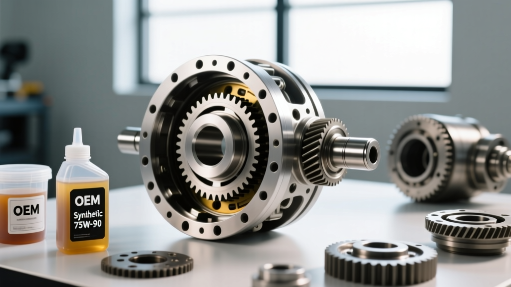
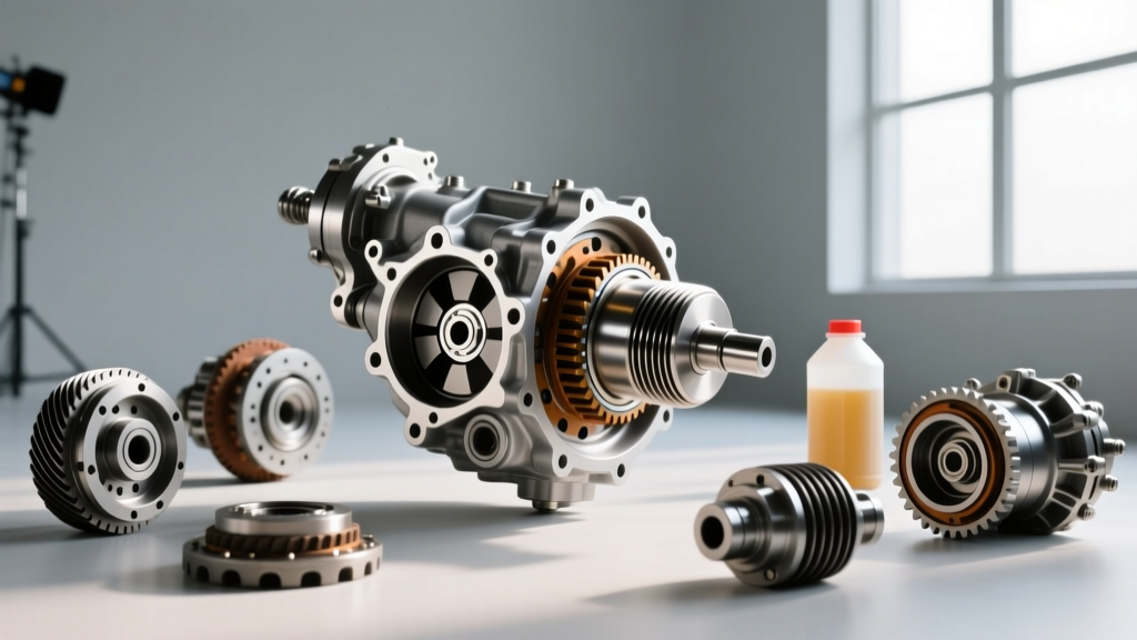
When most automotive technicians and enthusiasts think of differential rebuild procedures, they picture splash-lubricated passenger car axles like the Ford 8.8 or the classic Dana 44. However, the landscape of drivetrain engineering has evolved significantly. Modern heavy-duty commercial axles (such as the Dana Spicer S-Series and Meritor RT-Series), advanced EV reduction gearboxes, and high-performance AWD transfer cases utilize pressurized lubrication systems. These systems feature external or PTO-driven oil pumps and remote filtration circuits equipped with a differential pressure indicator.
If you are performing a rebuild on a pressurized axle assembly in 2026, ignoring the filtration circuit and its monitoring indicators is a guaranteed path to catastrophic pinion bearing failure. This step-by-step how-to guide will walk you through the critical phases of a heavy-duty differential rebuild, with a specific focus on testing, servicing, and validating the differential pressure indicator and lube system.
Why the Differential Pressure Indicator Matters
In a pressurized differential, oil is pumped through a filter before reaching the pinion bearings and planetary hubs. Over time, metallic wear particles and carbon sludge clog the filter media. The differential pressure indicator (often a mechanical pop-up flag or an electronic Hall-effect switch) monitors the pressure drop ($\Delta P$) across the filter.
- Normal Operation: Clean oil flows freely; $\Delta P$ remains below 10 PSI.
- Clogged Filter: Flow restriction causes $\Delta P$ to spike. Once it hits the threshold (typically 15–25 PSI), the indicator trips, alerting the driver or telematics system.
- Bypass Mode: Simultaneously, an internal bypass valve opens to allow unfiltered oil to reach the gears, preventing immediate oil starvation at the cost of accelerated wear.
During a rebuild, you must ensure this indicator is not only replaced or cleaned but functionally tested to guarantee it will trip at the correct threshold.
Tools and Specifications for the Rebuild
Before beginning the teardown, gather your precision measuring tools and OEM reference materials. For this guide, we are referencing specifications common to heavy-duty single-reduction axles (e.g., Dana S130/S160 series).
| Component / Parameter | Specification / Torque | Tool Required |
|---|---|---|
| Pinion Nut (Heavy Duty) | 600 - 850 lb-ft | 1" Drive Torque Multiplier |
| Bearing Cap Bolts | 350 - 400 lb-ft | Torque Wrench (1/2" or 3/4") |
| Ring Gear Backlash | 0.012" - 0.016" | Dial Indicator & Magnetic Base |
| Filter Bypass / Indicator Trip Point | 18 - 22 PSI ($\Delta P$) | Hand-held Pneumatic Pressure Pump |
| Housing Leak-Down Test | 3 - 5 PSI (Static Air) | Manometer & Axle Seal Installer |
Step-by-Step Differential Rebuild Procedure
Step 1: Teardown and Housing Preparation
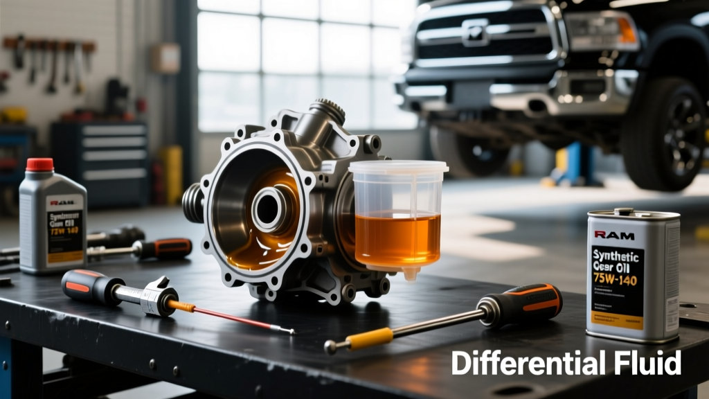
Begin by draining the axle housing. Heavy-duty axles can hold 15 to 30 gallons of 80W-140 synthetic gear oil. Once drained, remove the axle shafts and the differential carrier.
Critical Step: Carefully unscrew the differential pressure indicator switch from the filter housing using a deep well socket. These are often installed with heavy-duty thread sealant. Apply localized heat (up to 250°F) with a heat gun if the switch is seized to avoid cracking the cast aluminum or iron filter head. Clean the housing thoroughly with a non-chlorinated brake cleaner and compressed air.
Step 2: Ring and Pinion Setup
With the carrier on the bench, press off the old bearings. Install the new pinion bearing cone and set your pinion depth using the OEM shim calculator or the marking compound method.
- Pinion Depth: Adjust the pinion depth shim until the contact pattern on the ring gear is centered on the tooth face, slightly biased toward the heel under no load.
- Backlash: Mount the dial indicator perpendicular to the ring gear teeth. Adjust the side bearing shims or adjuster nuts to achieve 0.014" of backlash.
- Preload: Torque the bearing cap bolts to 350 lb-ft. Verify that the total rolling torque (pinion preload + carrier preload) falls within the manufacturer's specification, typically 45-65 in-lbs for new bearings.
Step 3: Lube Pump and Differential Pressure Indicator Service
This is where pressurized rebuilds diverge from standard automotive procedures. Do not reuse the old lube filter or the old indicator switch if it shows signs of mechanical fatigue.
- Replace the Filter Element: Install a new OEM filter kit (e.g., Dana Part # KIT-133885 or Meritor A1205W1117). Lubricate the O-rings with clean gear oil before seating.
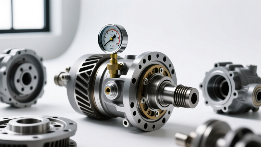
- Test the Indicator: Connect a hand-held pneumatic pressure pump to the sensor port of the differential pressure indicator. Slowly increase the pressure. The mechanical flag should pop out, or the multimeter should show continuity on the electrical pins exactly between 18 and 22 PSI. If it trips at 10 PSI or fails to trip at 30 PSI, replace the indicator immediately.
- Reinstall: Apply a high-temperature anaerobic thread sealant (like Loctite 545) to the indicator threads and torque to 25 lb-ft.
Step 4: Seal Installation and Static Pressure Testing
Before filling the axle with expensive synthetic fluid, you must verify housing integrity. Install the pinion seal and axle shaft seals using the proper stepped mandrels to avoid cutting the sealing lips.
Plug the axle breather and the fill port. Introduce low-pressure compressed air (3 to 5 PSI) into the housing via a modified fill plug equipped with a schrader valve. Spray a soapy water solution around the pinion seal, axle seals, and the differential pressure indicator threads. Any bubbling indicates a leak that must be addressed before the axle is put into service.
Common Failure Modes and Diagnostics
Even after a meticulous rebuild, issues can arise during the initial fill and test drive. Here is how to diagnose post-rebuild filtration anomalies:
Pro-Tip from the Bench: If the differential pressure indicator trips immediately upon startup after a rebuild, do not assume the filter is defective. In cold climates, using an 80W-140 fluid instead of a 75W-90 synthetic can cause massive cold-flow restriction, triggering a false $\Delta P$ spike until the fluid warms up. Always verify the 2026 OEM fluid viscosity requirements for your specific operating environment.
- Premature Indicator Tripping: Often caused by a collapsed filter media (defective part), incorrect fluid viscosity, or a stuck bypass spring in the filter head.
- Indicator Never Trips (Even with Clogged Filter): The internal bypass valve may be stuck open due to a piece of RTV silicone or casting sand left in the housing during the rebuild. This starves the pinion bearings of oil pressure.
- Pinion Bearing Whine Post-Rebuild: If the gear pattern was correct but the bearings fail early, check the lube pump output. A failing pump will not push oil to the top of the carrier, regardless of what the differential pressure indicator reads.
Conclusion
Rebuilding a pressurized differential requires a paradigm shift from traditional splash-lubricated axles. By treating the lube filtration circuit and the differential pressure indicator as critical, precision components rather than mere accessories, you ensure the longevity of the ring and pinion set. Always consult the latest technical bulletins via Dana Technical Resources or the Meritor Support Portal to verify torque specs and fluid capacities for your exact axle serial number before turning the first wrench.