The Blueprint of Axle Noise: Why the Diagram Matters
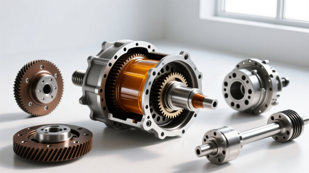
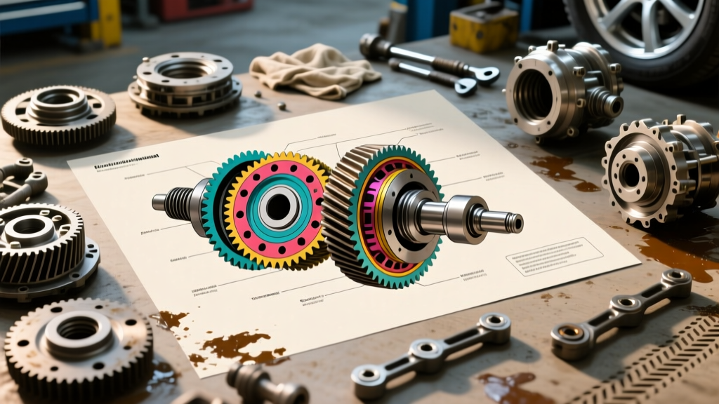
When a vehicle rolls into the shop with a whining, howling, or clunking rear end, novice mechanics often jump straight to tearing down the carrier. However, seasoned drivetrain specialists know that accurate diagnosis begins long before a wrench is turned. It starts with a detailed study of a differential gear diagram. As we navigate the 2026 landscape of high-torque towing platforms, aggressive off-road builds, and heavy-duty EV conversions, axle components are subjected to unprecedented stress. Understanding the exact load paths, gear geometry, and bearing preload points illustrated in a factory differential gear diagram is the only reliable way to map a specific auditory symptom to a failing internal component.
A standard hypoid gear set operates with extreme sliding friction. The pinion gear sits below the centerline of the ring gear, creating a complex mesh pattern that shifts dynamically between the 'drive' and 'coast' sides of the gear teeth depending on throttle input. By cross-referencing the noise profile with the diagram, you can isolate whether the issue stems from pinion depth, carrier backlash, bearing preload, or spider gear wear.
Expert Pro-Tip: Never diagnose axle noise based on sound alone while the vehicle is on a lift. Tires on concrete, wheel bearings, and transmission output shafts can mask or mimic differential noise. Always perform a coast-down and load-test on asphalt, then verify with a chassis ear or mechanic's stethoscope on the shop floor.
Mapping Sound to the Differential Gear Diagram
To effectively troubleshoot, you must understand how the components labeled on your differential gear diagram interact under load. Below is a diagnostic matrix mapping common axle noises to their corresponding diagram components and root causes.
| Auditory Symptom | Driving Condition | Diagram Component | Probable Root Cause & Fix |
|---|---|---|---|
| Steady Whine | Acceleration (Load) | Ring & Pinion (Drive Side) | Pinion depth is too shallow or gear wear. Requires pinion shim adjustment and pattern verification. |
| Howling | Deceleration (Coast) | Ring & Pinion (Coast Side) | Pinion depth is too deep or backlash is too tight. Check pinion bearing preload. |
| Rumble / Growl | Above 20 MPH (Any) | Carrier / Pinion Bearings | Bearing race pitting or improper crush sleeve preload. Replace bearings and reset preload. |
| Metallic Clunk | Shift from Reverse to Drive | Spider & Side Gears | Excessive side gear clearance, worn cross pin, or stripped axle splines. Inspect carrier internals. |
| Chatter / Binding | Low-Speed Tight Turns | LSD Clutch Packs | Depleted friction modifier in the gear oil. Drain, refill with 75W-90 GL-5, and add 4oz modifier. |
The Expert Troubleshooting Workflow
Once you have used the differential gear diagram to form a hypothesis based on the noise matrix, follow this systematic diagnostic workflow to confirm the failure mode before ordering parts.
Step 1: Magnetic Plug and Fluid Analysis
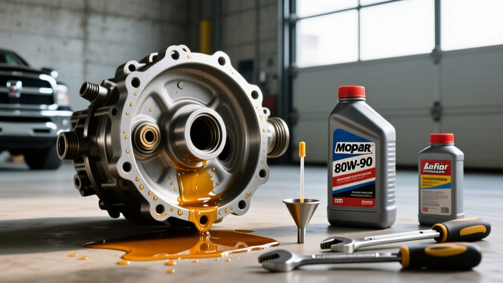
Draining the differential fluid is your first physical look inside the housing. The condition of the fluid and the magnetic drain plug tell a detailed story. According to the Dana Spicer Technical Manuals, a fine, dark gray metallic paste on the magnet is normal wear for hypoid gears. However, if you find shiny, needle-like splinters, your pinion or carrier bearings are disintegrating. If you find chunky, jagged metal shards, the ring and pinion teeth are spalling or the spider gear cross pin has sheared.
For fluid selection, modern synthetic formulations are mandatory for longevity. We recommend a high-quality 75W-90 or 75W-140 GL-5 synthetic gear oil (such as Motul Gear 300 or AMSOIL Severe Gear). If your differential gear diagram indicates a limited-slip differential (LSD) with clutch-style packs (like the Ford 8.8 Traction-Lok or GM G80), you must add a dedicated friction modifier (e.g., Motorcraft XL-3) to prevent low-speed cornering chatter.
Step 2: Backlash and Runout Measurement
Before pulling the carrier, mount a magnetic dial indicator on the housing. Position the probe perpendicular to the ring gear teeth. Rotate the ring gear back and forth while holding the pinion yoke stationary.
- Standard Backlash Spec: Typically 0.006' to 0.010' (check your specific OEM diagram).
- Runout Spec: Maximum 0.003' variation around the entire gear rotation.
Step 3: Gear Contact Pattern Verification
Apply a generous coat of yellow gear-marking compound to three or four consecutive teeth on both the drive and coast sides of the ring gear. Rotate the pinion to move the gears through the mesh. Compare the resulting pattern to the reference charts provided in the Ring-Pinion.com Master Setup Guide.
A pattern biased toward the toe (inner edge) indicates the pinion is too close to the ring gear (requires a thicker pinion depth shim). A pattern biased toward the heel (outer edge) means the pinion is too far away. A pattern riding high on the tooth flank indicates backlash is too wide. This visual confirmation, grounded in the geometry shown on your differential gear diagram, is the ultimate arbiter of gear health.
Critical Torque Specifications and Setup Data
When your diagnosis leads to a teardown and rebuild, adhering to exact torque specifications is non-negotiable. Improper torque leads to shifting preload, destroyed crush sleeves, and catastrophic gear failure under load. Below are baseline specifications for two of the most common differentials on the road.
Ford 8.8-Inch (Solid Rear Axle)
- Ring Gear to Carrier Bolts: 70-85 ft-lbs (Apply medium threadlocker, e.g., Loctite 242, to the threads).
- Carrier Bearing Cap Bolts: 70-85 ft-lbs (Must be marked and reinstalled in their original orientation to maintain bore roundness).
- Pinion Nut (Crush Sleeve Design): 200-250 ft-lbs. Warning: Tighten in 5 ft-lb increments while measuring rotational torque. Target 8-14 in-lbs of rotational drag for used bearings, or 16-29 in-lbs for new bearings. Over-crushing the sleeve requires a new sleeve and a complete teardown to reset.
Dana 44 (Jeep / Light Truck Applications)
- Ring Gear Bolts: 60 ft-lbs (Left-hand threads on some early models; verify with your specific differential gear diagram).
- Pinion Nut (Crush Sleeve): 220-260 ft-lbs. Target rotational preload of 12-18 in-lbs.
- Carrier Bearing Adjuster Nuts (if equipped): Tighten until backlash is within 0.006'-0.010', then torque the bearing cap bolts to 60 ft-lbs.
Upgrading to Solid Pinion Spacers
One of the most valuable best practices derived from studying heavy-duty differential gear diagrams is the elimination of the crush sleeve. The crush sleeve is a one-time-use spacer designed to set pinion bearing preload at the factory. However, it is highly susceptible to collapsing under heavy shock loads (e.g., rock crawling, heavy towing, or aggressive drag racing launches). When it collapses, pinion preload is lost, the pinion gear wobbles, and the ring and pinion teeth are destroyed in a matter of miles.
As a best practice for any rebuild, replace the crush sleeve with a solid pinion spacer kit (such as those offered by Yukon Gear & Axle or Ratech). These kits utilize a solid steel spacer paired with a selection of precision shims. While it takes more time to dial in the exact shim thickness to achieve the correct rotational torque, the result is a bulletproof pinion preload that will never collapse, regardless of the torque applied to the yoke nut.
Final Thoughts on Drivetrain Diagnostics
Diagnosing differential noise is a discipline that rewards patience, precision, and a deep respect for mechanical geometry. By anchoring your troubleshooting process to a comprehensive differential gear diagram, you transition from a parts-swapper to a true drivetrain specialist. Whether you are setting up a 4.56 gear set for a dedicated off-roader or simply chasing down a high-speed highway whine in a daily driver, the principles of load-path analysis, precise measurement, and exact torque application remain universal. Always consult the Differential Technical Information archives for model-specific variations, and never cut corners on gear oil chemistry or bearing quality.