The Intersection of Hydraulics and Gear Lubrication
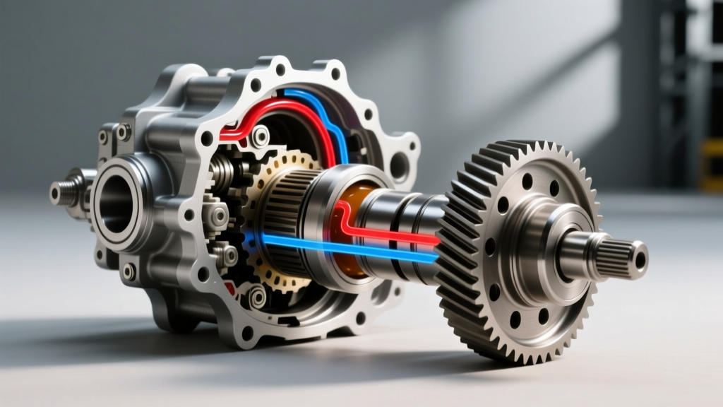
As we navigate the 2026 automotive landscape, the modern drivetrain is no longer just a collection of hardened steel gears; it is a complex hydraulic and thermal management system. Whether you are servicing the rear axle of a heavy-duty tow rig, a high-performance AWD crossover, or an electric vehicle with an integrated e-Axle, the differential fluid change procedure demands far more than simply draining and filling. Master technicians now integrate fluid dynamics and thermal diagnostics into routine maintenance. Specifically, understanding and applying a differential pressure formula is critical for diagnosing breather restrictions, preventing seal extrusion, and ensuring proper hydraulic actuation in electronic limited-slip differentials (eLSDs).
Service Intervals: Debunking the 'Lifetime' Fluid Myth
Many OEMs market their synthetic gear oils as 'lifetime' fluids. In the context of commercial fleet and severe-duty consumer use, 'lifetime' simply means the lifetime of the warranty. For trucks towing over 8,000 lbs, off-road SUVs, and performance vehicles, the extreme shear forces and thermal cycling degrade the viscosity index improvers in 75W-90 and 75W-85 synthetic gear oils long before the 150,000-mile mark.
- Standard Highway Driving: Inspect at 60,000 miles; replace at 100,000 miles.
- Severe Duty (Towing, Off-Road, Track): Replace every 40,000 to 50,000 miles.
- Submerged/Water Crossing Events: Immediate replacement required, as water ingress emulsifies the gear oil, destroying its extreme pressure (EP) additive film strength.
The Breather Vent and the Differential Pressure Formula
Before unbolting a single drain plug, a critical diagnostic step involves the axle breather vent. As differential fluid heats up during operation, the air inside the axle housing expands. If the breather vent is clogged with mud, debris, or ice, the internal housing pressure spikes. Technicians use a manometer and a basic differential pressure formula to verify housing integrity:
ΔP = Pinternal - Patmospheric
Where ΔP is the differential pressure across the axle seals.
Most modern synthetic rubber axle shaft and pinion seals are designed to withstand a maximum ΔP of roughly 3.5 to 5.0 PSI. If a clogged breather causes the internal pressure to exceed this threshold, the differential pressure forces the seals to extrude and leak. If you perform a fluid change without clearing a restricted breather, the newly filled housing will simply blow out the pinion seal the next time it reaches operating temperature, contaminating your brake rotors and destroying the new gear oil.
Step-by-Step Differential Fluid Change Procedure
Step 1: Axle Breather & ΔP Verification
- Locate the axle breather tube (usually routed high up on the chassis or attached directly to the differential cover).
- Remove the cap and inspect for carbon buildup or debris.
- If equipped with a remote tube, ensure the check-valve cap is not fused shut. A functioning breather should allow free airflow, maintaining a ΔP of near zero during thermal expansion.
Step 2: Fluid Extraction and Metallurgical Inspection
- Remove the fill plug first. Never remove the drain plug or drop the cover before verifying the fill plug is free. A seized fill plug with an empty axle housing is a shop-killer.
- Drain the fluid into a calibrated catch pan. Inspect the drain plug magnet.
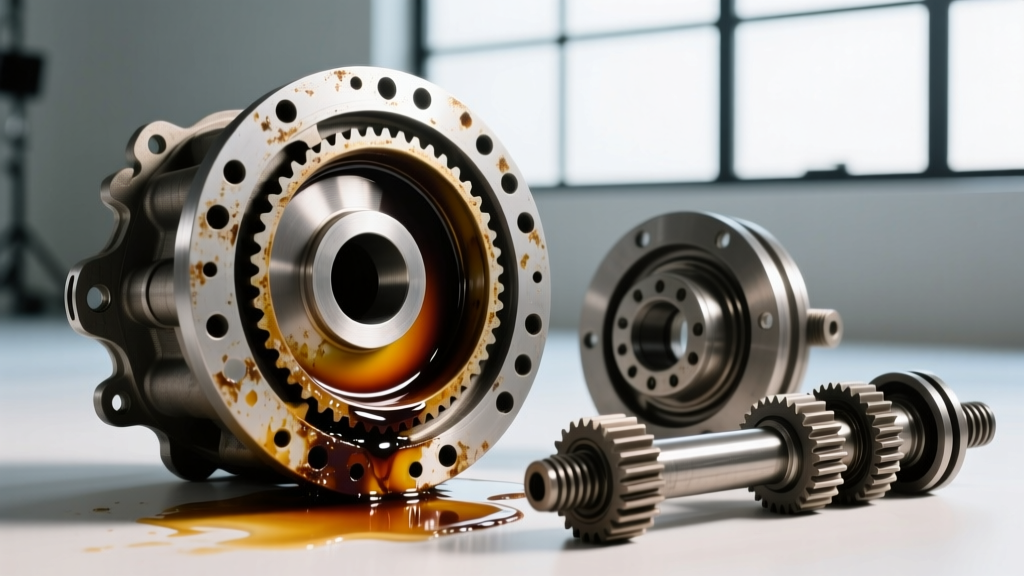
- Diagnostic Note: Fine, glitter-like metallic paste is normal wear from the ring and pinion gears. However, chunky metallic shards or brass-colored flakes indicate catastrophic bearing cage failure or bronze thrust washer disintegration, requiring a full teardown.
Step 3: Housing Resealing and Cleaning
- If your axle uses a differential cover (e.g., GM 9.5-inch 14-bolt, Ford 10.5-inch), clean the mating surfaces with a dedicated brake cleaner or non-chlorinated parts cleaner.
- Apply a 3mm continuous bead of high-temperature RTV silicone (such as Permatex Ultra Black or The Right Stuff). Do not over-apply; excess RTV will break off inside the housing and clog the eLSD gerotor pump pickup screen.
- Torque the cover bolts in a crisscross pattern to the manufacturer's specification (typically 30-45 lb-ft).
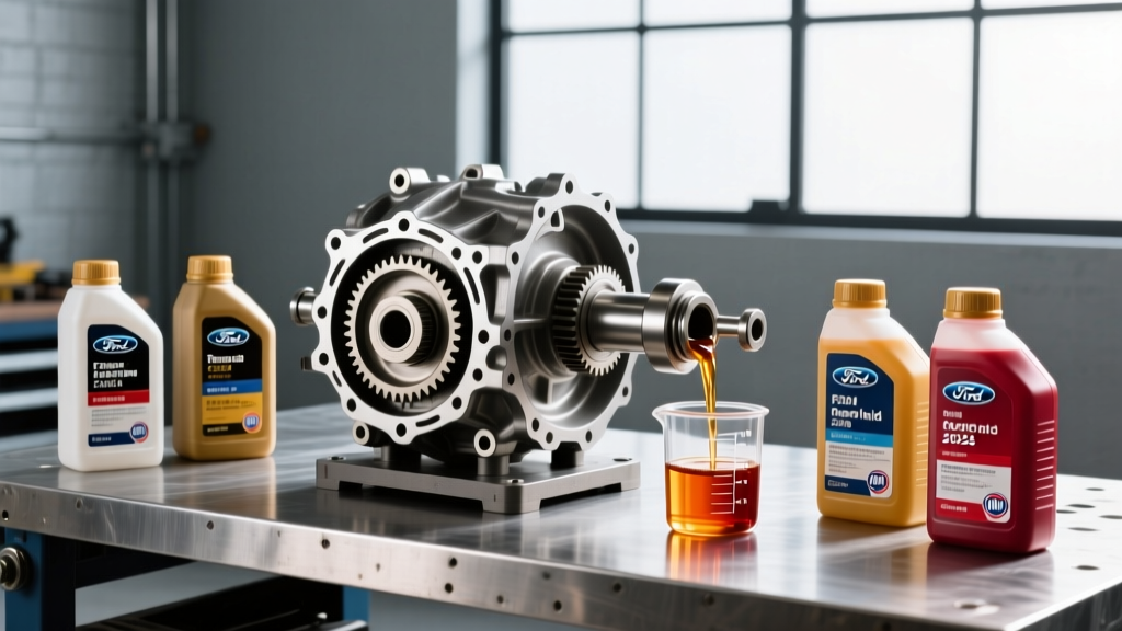
Step 4: Precision Filling and Additive Calibration
- Fill the differential until the fluid reaches the bottom edge of the fill hole. For vehicles with independent rear suspension (IRS) or specific pinion angles, consult the OEM manual, as some require the fluid level to be 1/2 inch below the fill plug.
- Reinstall the fill plug and torque to spec.
Fluid Capacities and Torque Specifications Matrix
| Axle Assembly | OEM Fluid Specification | Capacity | Fill/Drain Torque | Cover Torque |
|---|---|---|---|---|
| GM 9.5' (14-Bolt Semi-Float) | ACDelco 75W-85 Synthetic (88862624) | 3.0 Pints | 24 lb-ft | 30 lb-ft |
| Ford 10.5' (Super Duty/Tremor) | Motorcraft 75W-140 Synthetic (XL-5) | 3.5 Pints | 35 lb-ft | N/A (Drop axle) |
| Ram ZF 235mm Rear | Mopar 75W-85 Synthetic | 2.4 Liters | 30 lb-ft | 35 lb-ft |
| Toyota 8.0' (Tundra/Tacoma) | Toyota 75W-85 GL-5 | 2.8 Pints | 29 lb-ft | N/A (Drop axle) |
eLSD Viscosity and the Hagen-Poiseuille Differential Pressure Formula
The integration of electronic limited-slip differentials (eLSDs) and active torque-vectoring axles has fundamentally changed fluid requirements. Systems like the GM G80, Ford eLocker, and ZF EC60 rear drive modules utilize internal gerotor pumps and micro-valves to actuate clutch packs. The fluid flow through these microscopic orifices is governed by the Hagen-Poiseuille equation, a specific differential pressure formula used in fluid dynamics:
ΔP = (8 μ L Q) / (π r4)
In this formula, ΔP is the pressure drop, μ is the dynamic viscosity of the gear oil, L is the length of the orifice, Q is the flow rate, and r is the radius of the valve. Because the radius is to the fourth power, even minor deviations in fluid viscosity (μ) cause massive spikes in the required differential pressure (ΔP).
The Real-World Consequence: If an OEM specifies a 75W-85 gear oil for an eLSD, and a technician substitutes it with a thicker 80W-90 or 75W-140 fluid, the dynamic viscosity (μ) increases. According to the differential pressure formula, the internal gerotor pump must generate significantly higher ΔP to push the thicker fluid through the clutch pack micro-valves. This leads to delayed locking engagement, clutch pack shudder, and eventual hydraulic starvation, resulting in burnt friction material. Always adhere strictly to the OEM viscosity grade, referencing standards like the SAE J306 Standard for driveline lubricants.
The Friction Modifier Myth
Another area where technicians falter is the use of friction modifiers. Clutch-type limited-slip differentials (like the Ford Trac-Lok or Eaton Posi) absolutely require a friction modifier (e.g., Motorcraft XL-3 or ACDelco 88900331) to prevent chatter during low-speed cornering. However, mechanical locking differentials (like the GM G80) and Torsen (torque-sensing) gear-type differentials do not use clutch packs for their primary locking mechanism. Adding friction modifier to a G80 or Torsen differential reduces the coefficient of friction on the internal thrust washers and helical gears, accelerating wear and reducing torque bias ratios. Always verify the differential type before adding aftermarket additives.
Final Diagnostics and Road Testing
After completing the differential fluid change procedure, a proper road test is mandatory. Drive the vehicle in a series of tight, slow-speed figure-eights in an empty lot. This forces the differential gears to articulate and cycles the new fluid through the internal passages, purging any trapped air pockets from the eLSD hydraulic circuits. Listen for whining or howling, which could indicate improper gear lash or the use of an incorrect fluid viscosity altering the acoustic damping properties of the oil film.
By combining meticulous mechanical procedures with an understanding of thermal expansion and the differential pressure formula, you ensure the longevity of the axle assembly, protect expensive electronic actuators, and maintain optimal traction in all driving conditions. For further reading on modern driveline tribology, consult resources from Lubrizol Driveline Engineering.