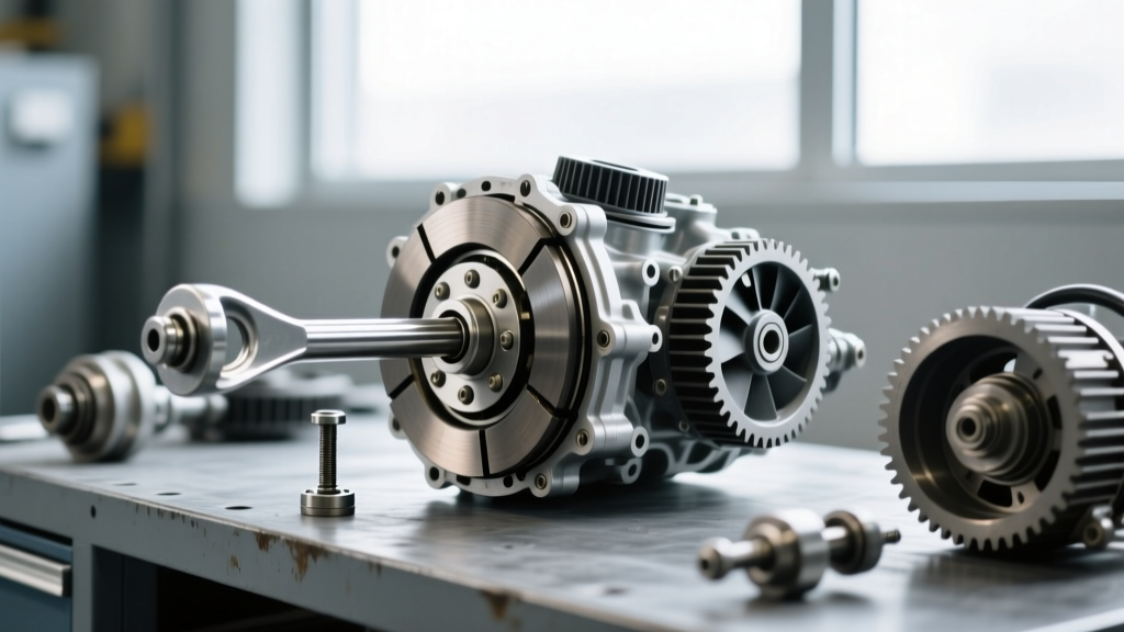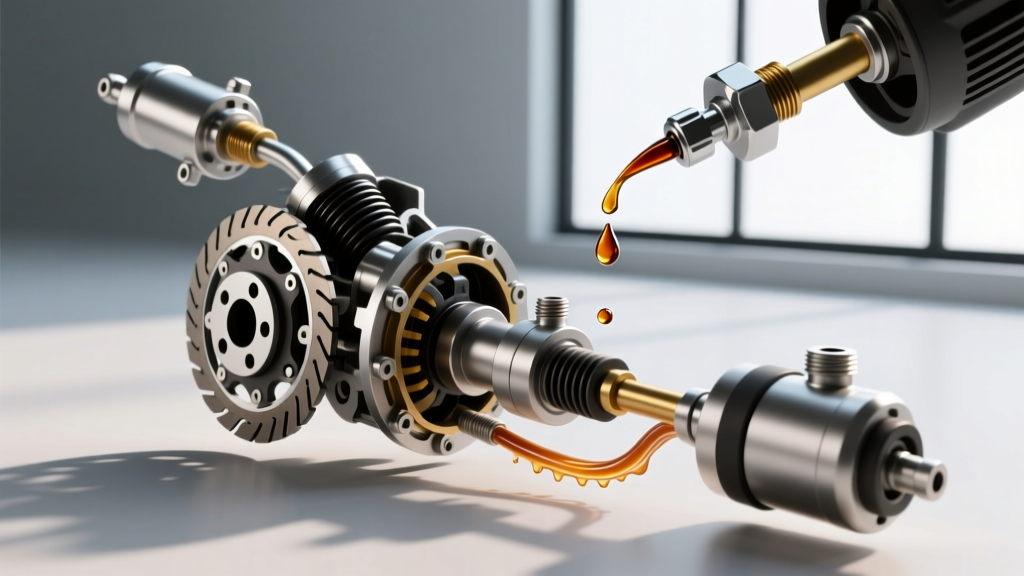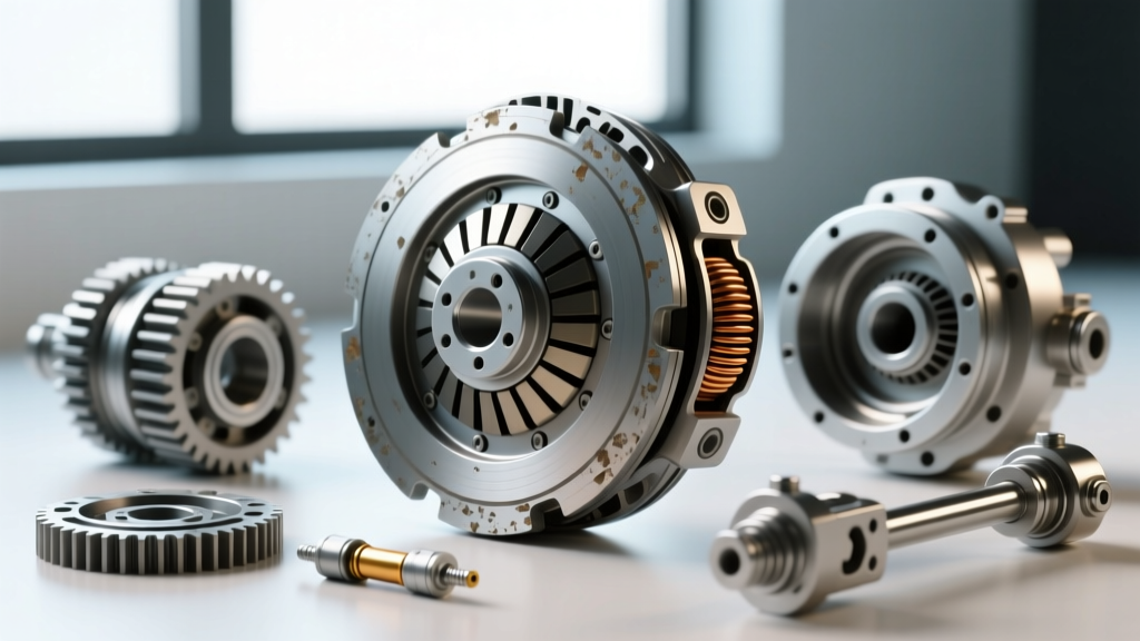
The Thermodynamics: How a Fan Clutch Works
While drivetrain enthusiasts typically associate the word 'clutch' with manual transmission friction discs or automatic torque converter lock-up mechanisms, the engine cooling system relies on a remarkably complex viscous coupling device: the fan clutch. Understanding how a fan clutch works is essential for diagnosing thermal management failures, parasitic horsepower loss, and catastrophic bearing degradation. At its core, a thermal fan clutch operates using a high-viscosity silicone fluid (typically ranging from 10,000 to 60,000 centistokes) contained within a precision-machined rotor and stator assembly.
When the engine is cold, the fluid resides in a reservoir chamber. As the radiator's ambient air temperature rises, a bimetallic thermostatic coil on the face of the clutch expands. This mechanical expansion opens a micro-valve, allowing the silicone fluid to migrate into the working chamber between the grooved rotor (driven by the water pump shaft) and the stator (attached to the cooling fan). The sheer friction of the fluid dragging across these microscopic grooves transfers torque to the fan blades, pulling critical CFM (Cubic Feet per Minute) of air across the radiator and AC condenser.
Critical Wear Signs and Failure Modes
Because the fan clutch operates in a high-heat, high-vibration environment at the front of the engine bay, its internal components are subject to severe thermal cycling. Identifying clutch wear signs early prevents secondary failures, such as blown head gaskets from overheating or shattered fan blades destroying a radiator. Here are the primary failure modes:
1. Viscous Degradation (Slipping)
Silicone fluid loses its shear stability over time. When subjected to thousands of thermal cycles, the fluid's molecular chains break down, reducing its viscosity. A slipping fan clutch will fail to engage fully at idle or under heavy towing loads. The primary symptom is a gradual rise in engine coolant temperature during low-speed, high-load scenarios (like crawling in 4WD or idling in traffic with the AC on max), while highway cruising temperatures remain normal due to passive ram-air cooling.
2. Mechanical Seizure (Locked Clutch)
Internal scoring, bearing collapse, or a jammed bimetallic valve can cause the clutch to remain in the fully engaged position permanently. A seized fan clutch creates massive parasitic drag on the water pump and serpentine belt system. You will hear a distinct 'roaring' or 'jet engine' noise immediately upon cold startup that does not dissipate as the engine warms up. In extreme cases, the rotational stress can snap the fan blades or destroy the water pump bearings.
3. Bearing and Seal Wear
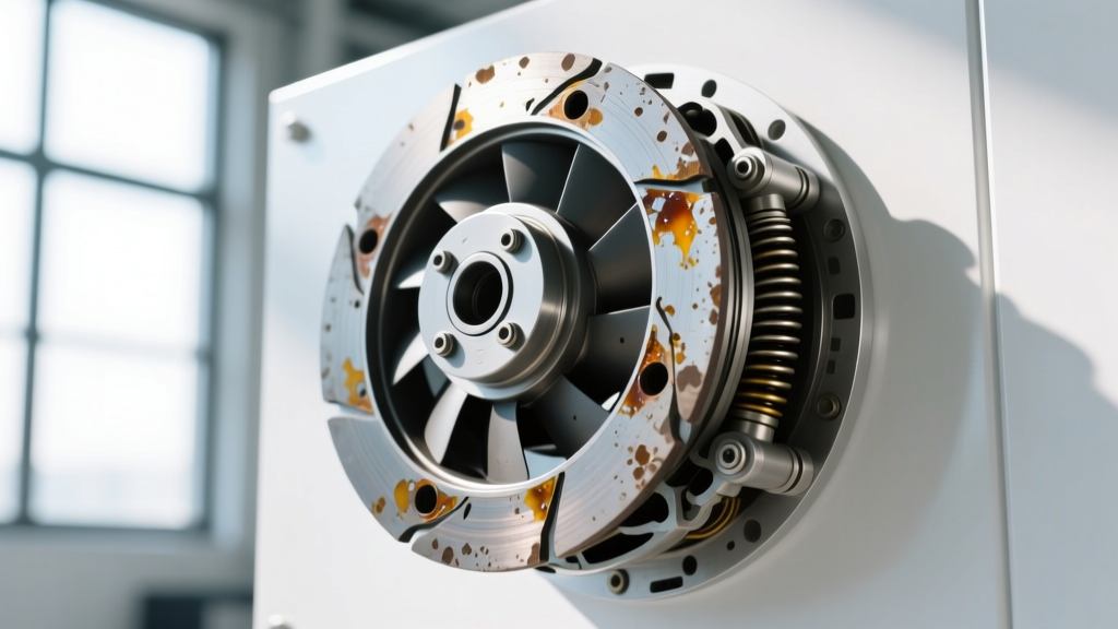
The pilot bearing supporting the clutch assembly is sealed, but extreme heat bakes the grease, leading to axial and radial play. If you grab the fan blade (with the engine off and cool) and wiggle it up and down, any deflection greater than 1/16th of an inch indicates bearing failure. Additionally, look for a ring of oily residue or dust accumulation around the clutch shaft—this is a definitive sign of silicone fluid leaking past the primary O-ring seal.
Diagnostic Matrix: Symptoms vs. Root Causes
Use the following diagnostic table to cross-reference your vehicle's symptoms with the appropriate mechanical verification test.
| Symptom | Probable Root Cause | Diagnostic Verification Test | Corrective Action |
|---|---|---|---|
| Overheating at idle / AC cuts out | Fluid shear degradation (Slipping) | Infrared temp gun on clutch face; should read >160°F when engaged | Replace fan clutch assembly |
| Constant roaring noise, high RPM drag | Internal valve seizure or fluid lock | Cold startup test: fan should spin freely for 30-60 seconds | Replace clutch and inspect water pump |
| Wobble, squealing, or rattling | Pilot bearing failure | Static deflection test (>1/16' play at blade tip) | Replace clutch; check shaft runout |
| Erratic engagement, check engine light | PWM solenoid or wiring fault | OBD2 scan for codes P0480-P0485; oscilloscope signal check | Repair harness or replace PWM unit |
Lifespan Indicators and Mileage Benchmarks
The lifespan of a viscous fan clutch is heavily dictated by the vehicle's duty cycle. According to engineering data from Hayden Automotive, a standard thermal fan clutch in a commuter vehicle typically lasts between 80,000 and 120,000 miles. However, lifespan indicators drop dramatically in severe-duty applications.
- Heavy Towing / Off-Road (Diesel Trucks): 50,000 - 70,000 miles. Constant high-radiator-ambient-temps keep the bimetallic spring fully expanded, forcing the silicone fluid to work continuously without resting in the reservoir.
- Plow Vehicles / Salt Belt Commuters: Corrosion can seize the external bimetallic coil in as little as 40,000 miles, preventing the valve from closing when the engine cools.
- Modified Cooling Systems: Aftermarket radiators or missing fan shrouds alter the thermal envelope, often causing premature clutch cycling and accelerated fluid breakdown.
Advanced Diagnostics: PWM Electronic Fan Clutches
Modern heavy-duty platforms, such as the Ford 6.7L PowerStroke and the Ram 6.7L Cummins, have largely abandoned purely thermal bimetallic strips in favor of Pulse Width Modulated (PWM) electronic fan clutches. These units feature an internal electromagnetic valve controlled by the Powertrain Control Module (PCM). The PCM calculates the exact fan speed required based on coolant temp, AC pressure, and transmission fluid temp.
When diagnosing wear on a PWM clutch, mechanical symptoms mimic viscous units, but the root cause is often electrical. A common failure point on the GMT-900 and Ford Super Duty platforms is the wiring harness chafing against the AC accumulator or fan shroud, causing a short to ground. If the PCM detects an open or short circuit, it defaults the clutch to a 'fail-safe' locked state to protect the engine, resulting in a roaring fan and a P0480 (Fan Control Circuit) diagnostic trouble code. Always inspect the pigtail connector for corrosion or melted pins before condemning a $250+ electronic clutch assembly.
Expert Diagnostic Tip: Never rely solely on the 'newspaper test' (rolling up a newspaper and trying to stop the fan while running) to diagnose a modern heavy-duty clutch. The torque multiplication of modern water pumps and the sheer force of high-CFM blades can instantly destroy the fan blades, sending shrapnel through the radiator and posing a severe safety hazard. Always use thermal imaging and OBD2 bidirectional controls to command fan engagement safely.
Replacement Protocol: Torque, Threads, and Tools
Replacing a fan clutch requires specific tooling and an understanding of reverse-threaded fasteners. On the vast majority of GM LS/LT engines, Ford Modular V8s, and Chrysler HEMI platforms, the fan clutch nut securing the assembly to the water pump hub is left-hand thread (reverse thread). This prevents the rotational force of the water pump from unscrewing the clutch during operation.
To remove the clutch, you must hold the water pump pulley stationary while breaking the nut loose in a clockwise direction. This requires a specialized tool set, such as the OTC 4521 Fan Clutch Wrench Set (retailing around $85), which includes the specific 36mm, 47mm, or 58mm wrenches required for various OEM hubs.
Installation Specs and Part Numbers
When installing the replacement unit, thread the nut on counter-clockwise. While specific torque specs vary by OEM, the general industry standard for the fan clutch-to-water pump hub nut is 35 to 45 lb-ft. Always verify with the factory service manual, as some heavy-duty diesel applications require up to 65 lb-ft.
When sourcing parts, avoid unbranded overseas units that frequently use sub-standard silicone fluid with incorrect centistoke ratings, leading to immediate slipping. Trusted OEM and Tier-1 aftermarket part numbers include:
- Hayden 2722: Heavy-duty thermal clutch for GM 5.3L/6.0L trucks (Approx. $75 - $95)
- Motorcraft YB-3131: OEM replacement for Ford 6.7L PowerStroke electronic clutch (Approx. $280 - $340)
- GMB 930-2110: Premium aftermarket option for Toyota/Lexus V8 applications (Approx. $110 - $140)
Cost Analysis: OEM vs. Aftermarket in 2026
The cost to diagnose and replace a fan clutch varies significantly based on the actuation type and engine layout. For a standard longitudinal V8 gasoline truck, the job is straightforward. Expect to pay between $60 and $120 for a quality thermal clutch, with labor taking roughly 0.8 to 1.2 hours ($120 - $200 at independent shop rates). Total out-the-door cost usually lands between $200 and $350.
However, for modern diesel applications with PWM electronic clutches, or transverse-mounted engines where the clutch is buried behind tight shrouds and requires subframe manipulation, parts alone can exceed $300. Furthermore, if a seized clutch has damaged the water pump bearings due to excessive radial load, a concurrent water pump replacement is mandatory, pushing the total repair invoice past the $800 mark. For deeper insights into cooling system parasitic drag and mechanical load tolerances, refer to the technical papers published by SAE International regarding auxiliary engine cooling systems.
Ultimately, treating the fan clutch as a critical wear item—inspecting it for bearing play and fluid leaks during every major service interval—will save you from the catastrophic downstream costs of an overheated engine and a warped cylinder head.