Decoding Accessory vs. Drivetrain Clutch Noise
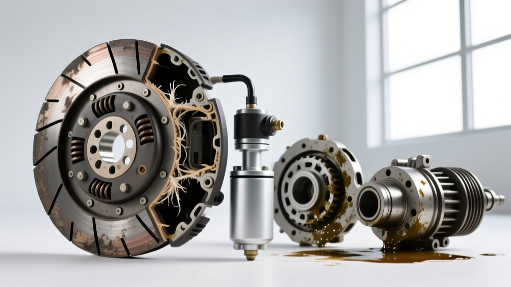
When a customer complains of a chirping, squealing, or grinding noise emanating from the front of their engine bay, novice technicians often immediately suspect the serpentine belt, tensioner, or even the primary drivetrain clutch assembly on manual transmission vehicles. However, as automotive diagnostic experts, we must isolate the accessory drive system—specifically, the air conditioning compressor clutch. The AC clutch is an electromagnetic friction device that engages and disengages the compressor pulley from the compressor shaft. Because it operates under high-heat, high-torque, and high-vibration conditions, it is highly susceptible to mechanical and electrical degradation.
Diagnosing clutch noise accurately is the first step before determining how to replace air conditioner compressor clutch assemblies effectively. Misdiagnosing a failing clutch coil as a bad compressor bearing can lead to unnecessary system evacuations and hundreds of dollars in wasted parts. This guide provides a master-level diagnostic framework and replacement protocol for modern AC compressor clutches.
The Diagnostic Matrix: Grinding, Squealing, and Chirping
Noise frequency, pitch, and operational state (whether the AC is commanded ON or OFF) are your primary diagnostic clues. Below is the definitive troubleshooting matrix for AC clutch noise diagnosis.
| Noise Profile | Operational State | Probable Root Cause | Diagnostic Verification Test |
|---|---|---|---|
| High-Pitch Chirping | AC Commanded ON | Clutch slippage due to wide air gap, low coil voltage, or high system head pressure. | Measure voltage at coil pigtail; check high-side manifold pressure; verify air gap with feeler gauge. |
| Continuous Squeal | AC Commanded OFF | Pulley bearing failure. The clutch hub is disengaged, but the pulley still spins on the snout bearing. | Remove serpentine belt, spin pulley by hand. Feel for gritty resistance or lateral play. |
| Metallic Grinding | AC Commanded ON | Severe hub wear, missing friction material, or compressor internal seizure transferring torque shock to the clutch. | Inspect friction surfaces for bluing. Check compressor shaft rotation with a spanner wrench. |
| Intermittent Clicking | Cycling ON/OFF | Weak electromagnetic coil, faulty relay, or low refrigerant charge causing rapid short-cycling. | Monitor clutch relay control signal via scan tool; check coil resistance (ohms). |
Deep Dive: The 'Chirp' and System Head Pressure
One of the most misdiagnosed symptoms in the Mobile Air Climate Systems Association (MACS) service bulletins is the chirping clutch. Technicians often replace the clutch, only for the noise to return a week later. Why? Because the clutch is slipping due to excessive mechanical load. If the condenser is blocked by debris, or the cooling fans are inoperative, the high-side refrigerant pressure can exceed 325 PSI. This extreme hydraulic resistance requires more torque to turn the compressor swashplate than the electromagnet can hold, resulting in friction surface slippage and a loud chirp. Always connect manifold gauges before condemning a slipping clutch.
Electrical Diagnostics: The Hidden Clutch Killer
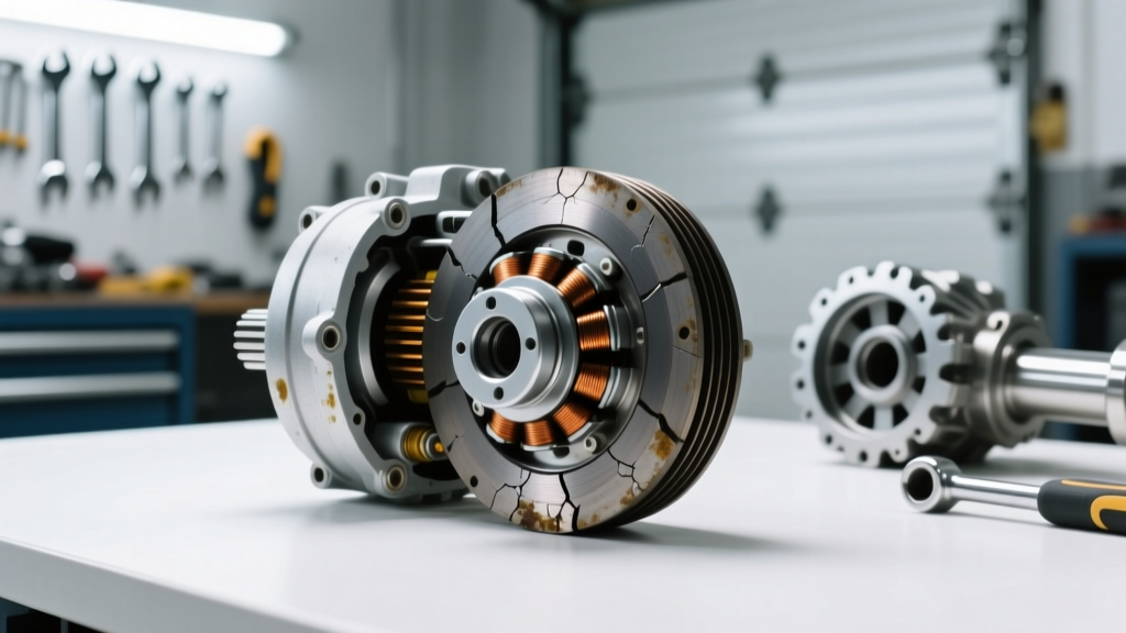
Before you reach for your snap-ring pliers, you must verify the electrical integrity of the clutch circuit. The electromagnetic coil requires a robust magnetic field to pull the friction hub against the pulley face. A weak magnetic field results in micro-slippage, generating immense heat that eventually melts the coil winding insulation and burns the friction material.
- Coil Resistance Test: Disconnect the clutch connector and measure resistance across the coil pins. A healthy 12V clutch coil (such as those found on Denso 10S17C or Harrison HT6 compressors) should read between 3.2 and 4.5 ohms at 68 degrees Fahrenheit. An infinite reading indicates an open circuit; a reading below 2.5 ohms indicates shorted windings.
- Voltage Drop Test: With the engine running and the AC commanded ON, back-probe the clutch connector. You must see battery voltage (typically 13.5V to 14.2V). If you measure only 11.0V at the coil, you have a voltage drop across the AC relay, wiring harness, or ground circuit. This voltage deficit drastically reduces the magnetic clamping force.
How to Replace Air Conditioner Compressor Clutch: Step-by-Step
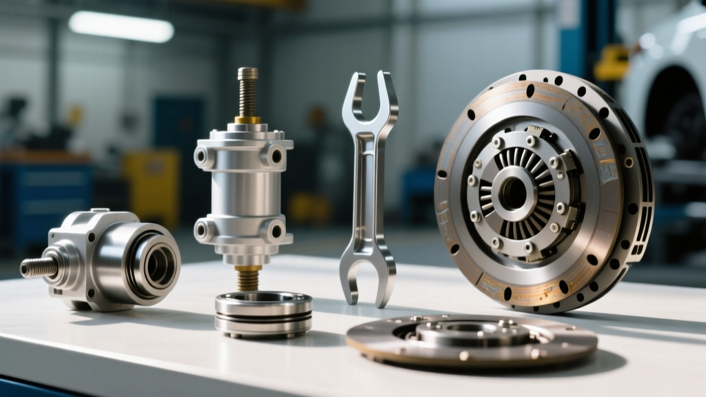
One of the greatest advantages of modern clutch design is that you rarely need to evacuate the refrigerant system to perform this repair. The clutch assembly is mounted externally on the compressor snout. Here is the professional procedure for clutch replacement.
Step 1: Safe Removal and Extraction
Begin by disconnecting the negative battery terminal. Remove the serpentine belt to eliminate tension on the pulley. Use a dedicated clutch holding tool (such as the OTC 4521 or Lisle 46000) to grip the friction hub. Break the center retaining bolt loose using an impact wrench or a long-handled ratchet. Note: Some older Ford and GM clutches use left-hand threads, though right-hand threads are standard on 90% of modern applications.
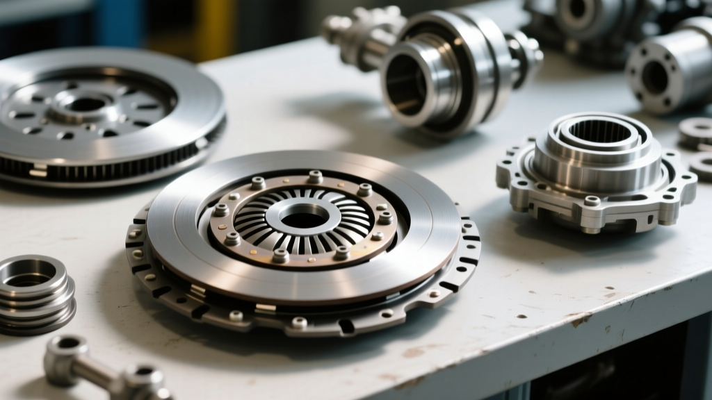
Once the bolt is removed, thread a clutch puller tool into the hub. Tighten the puller center screw against the compressor shaft to extract the hub. Next, use internal snap-ring pliers to remove the pulley retaining snap ring, and slide the pulley and bearing assembly off the snout. Finally, remove the electromagnetic coil snap ring and slide the coil off.
Step 2: Cleaning and Inspection
Clean the compressor snout and the internal bore of the new coil with brake cleaner. Inspect the snout for grooving or rust. If the snout is damaged, the new coil will not seat properly, leading to premature failure. Apply a microscopic film of PAG oil to the snout to prevent galvanic corrosion between the steel shaft and the aluminum/steel coil housing.
Step 3: Installation and the Critical Air Gap
Slide the new coil onto the snout, ensuring the anti-rotation tab aligns with the compressor housing notch. Install the coil snap ring. Press the new pulley assembly onto the snout until it bottoms out, then install the pulley snap ring.
Install the new friction hub and thread the center bolt by hand. This is where amateurs fail: The air gap between the friction hub and the pulley face must be precisely set. According to Denso Service Manuals, the standard air gap specification is 0.020 to 0.030 inches (0.5mm to 0.75mm). Use a feeler gauge to measure the gap at three equidistant points around the circumference.
- If the gap is too wide (>0.035 in): The magnet cannot fully engage the hub, causing slippage and chirping. Remove the hub and install a thinner shim washer onto the compressor shaft.
- If the gap is too narrow (<0.015 in): The clutch will drag when disengaged, causing continuous squealing, excessive heat, and rapid bearing wear. Remove the hub and add a thicker shim washer.
Step 4: Final Torque Specifications
Once the air gap is verified, torque the center retaining bolt to the manufacturer specification. For most GM, Ford, and Toyota applications utilizing M8 or M10 center bolts, the torque spec is 15 Nm to 20 Nm (11 to 15 lb-ft). Do not over-torque, as this can strip the threads in the compressor shaft or crush the internal shim stack, altering your carefully measured air gap.
Expert Best Practices for Long-Term Reliability
Replacing the physical components is only half the battle. To ensure the new clutch assembly survives beyond the warranty period, adhere to these master-technician best practices:
Pro-Tip: The Relay Swap Rule
Whenever a clutch coil burns out (verified by an open circuit or melted pigtail), always replace the AC compressor relay in the under-hood fuse box. A failing relay with pitted contacts causes high resistance and voltage drops, which is frequently the root cause that destroyed the clutch coil in the first place. A new clutch on a degraded relay circuit will fail within 5,000 miles.
Verify Condenser Airflow
As mentioned earlier, high head pressure destroys clutches. After installing the new clutch, use a scan tool to command the cooling fans to high speed. Verify that the condenser fins are not crushed or clogged with road debris. If the vehicle operates in harsh environments, recommend a condenser flush or replacement if thermal efficiency is compromised.
Refrigerant Charge Verification
While you do not need to recover the refrigerant to change the clutch, you must verify the system charge afterward. An undercharged system will cause the low-pressure switch to short-cycle the clutch rapidly, leading to mechanical fatigue of the hub splines and the clutch relay. Refer to the under-hood emissions label for the exact R-134a or R-1234yf capacity, and weigh in the charge using a calibrated recovery and recycling machine, in strict compliance with EPA Section 609 guidelines.
Summary of Costs and Part Selection
When sourcing parts, avoid ultra-cheap, no-name aftermarket clutch kits. The friction material on cheap kits often lacks the thermal binding agents required for high-load compression cycles. Expect to pay between $45 and $130 for a premium clutch kit (brands like Four Seasons, Denso, or OEM dealer parts). A dedicated clutch puller/installer tool kit will cost between $30 and $60 but is mandatory for preventing damage to the compressor snout threads. By combining rigorous noise diagnosis, electrical verification, and precision air-gap shimming, you elevate your service from a simple parts-swapper to a true automotive climate systems expert.