The Anatomy of Transmission Limp Mode
When a modern automatic transmission detects a critical fault, the Transmission Control Module (TCM) initiates a failsafe state commonly known as 'limp mode' or 'limp-home mode'. In this state, the TCM disables all shift solenoids, commanding maximum line pressure to prevent clutch slippage and catastrophic mechanical damage. The transmission defaults to a single gear—typically 3rd or 4th gear in older 4-speed and 6-speed units, or 5th gear in modern 8-speed and 10-speed platforms. Furthermore, the Torque Converter Clutch (TCC) lockup is disabled, and the driver information center will illuminate the malfunction indicator lamp (MIL) or a specific gear warning icon.
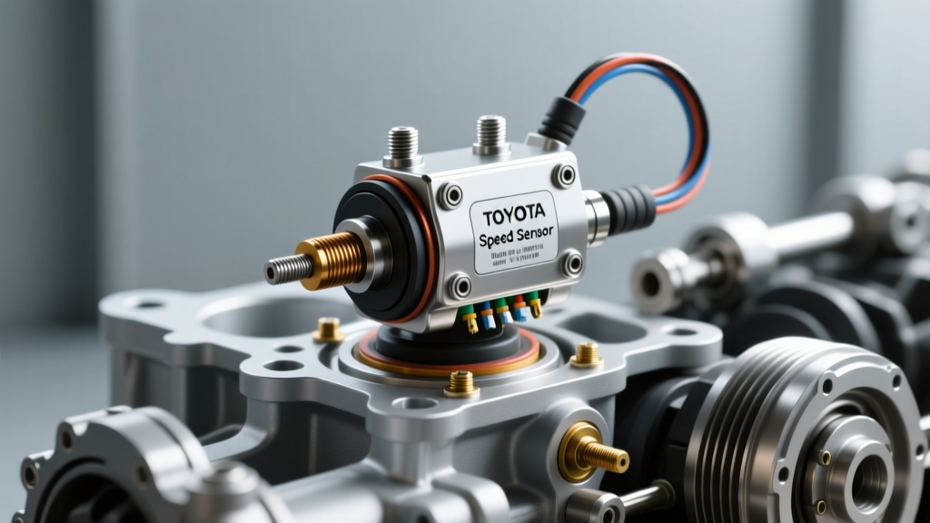
Speed sensor failures are among the most frequent culprits triggering this failsafe. Without accurate Input Shaft Speed (ISS) and Output Shaft Speed (OSS) data, the TCM cannot calculate slip across the clutch packs or determine the precise moment to command a shift. Understanding how to diagnose these faults is critical before you can accurately estimate the transmission sensor replacement cost for your specific vehicle.
Step 1: Code Extraction and Data PID Analysis
Diagnosis begins with a high-quality bi-directional scan tool capable of reading manufacturer-specific TCM Parameter IDs (PIDs). Generic OBD2 readers often fall short here. According to the OBD-Codes P0717 database, a code like P0717 (Input Speed Sensor Circuit No Signal) does not automatically mean the sensor is dead; it indicates the TCM is not seeing a plausible signal.
Follow this PID analysis framework:
- ISS vs. OSS RPM Comparison: With the vehicle safely on a lift and wheels spinning, monitor both ISS and OSS. If the OSS reads vehicle speed accurately but the ISS drops to 0 RPM or fluctuates wildly, you have isolated the fault to the input circuit.
- Calculated Gear Ratio: The TCM divides ISS by OSS to determine the current gear ratio. If the actual ratio deviates from the commanded ratio (e.g., P0731 - Gear 1 Incorrect Ratio), the TCM will trigger limp mode to protect the friction elements.
- Temperature PID Cross-Check: Speed sensors share internal TCM boards with fluid temperature sensors. If the Transmission Fluid Temperature (TFT) PID simultaneously reads -40°F or 300°F, you are likely looking at a shared 5V reference circuit failure or a melted internal harness, not just a standalone speed sensor.
Step 2: Electrical and Signal Verification
Modern transmissions utilize Hall-effect or Magneto-Resistive (MR) speed sensors, which output a digital square wave signal rather than the analog AC sine wave of older Variable Reluctance (VR) sensors. Testing requires a digital storage oscilloscope (DSO) or a high-impedance digital multimeter (DMM).
Using an automotive-specific DMM like the Fluke 88V, measure the reference voltage at the sensor connector with the key on, engine off (KOEO). A healthy Hall-effect sensor will show a steady 5V or 8V reference, depending on the OEM architecture. Backprobe the signal wire and rotate the output shaft by hand. The voltage should toggle cleanly between 0V and the reference voltage. If the voltage floats or drops to 2.5V, you have high resistance in the ground circuit or internal TCM driver failure.
Testing the GM 6L80 Input and Output Speed Sensors
The GM 6L80 and 6L90 transmissions present a unique diagnostic challenge. The ISS and OSS are not standalone components; they are permanently integrated into the Transmission Electro-Hydraulic Control Module (TEHCM). As noted by drivetrain specialists at Sonnax Tech Resources, diagnosing a 6L80 speed sensor fault requires verifying the 32-pin case connector first. Check for pushed-out pins, corrosion, or transmission fluid wicking up into the harness capillary. If the external harness and 5V reference/ground circuits test perfectly, the fault lies inside the TEHCM. You cannot replace just the sensor; the entire TEHCM must be replaced and flashed with the latest calibration files.
Testing the ZF 8HP Turbine and Output Speed Sensors
The ZF 8HP (found in BMW, Audi, Chrysler, and Ford vehicles) houses its turbine (input) and output speed sensors within the Mechatronic unit. To test the wiring, access the round ZF connector sleeve on the transmission case. Verify the 8V reference voltage supplied by the TCM. If the signal wire shows a clean 0V to 8V square wave on an oscilloscope when the output shaft is rotated by hand, the sensor is functional, and the fault may lie in the TCM logic board or the target wheel (tone ring) inside the transmission.
Step 3: Mechanical and Hydraulic Cross-Checks
Before condemning an electronic component, rule out mechanical interference. Speed sensors read off magnetic tone rings or reluctor wheels. If the transmission has suffered internal clutch failure, metallic debris and friction material can coat the magnetic tip of the sensor, blinding it to the tone ring.
Expert Insight: Always drop the transmission pan and inspect the fluid and filter before ordering electronic parts. A heavy accumulation of glitter or clutch material in the pan indicates a mechanical failure that will destroy a new sensor or TEHCM within miles of installation.
On Chrysler vehicles utilizing the ZF 8HP70 (badged as the 845RE or 850RE), the mechatronic unit is highly sensitive to fluid contamination. The integrated speed sensors rely on precise magnetic field reading. If the wrong fluid is used—such as standard ATF+4 instead of the mandatory ZF 8&9 Speed ATF—the friction modifiers will cause the clutch packs to shed excessive material, quickly blinding the internal speed sensors and triggering a P0716 or P0721 code.
Breaking Down the Transmission Sensor Replacement Cost
The transmission sensor replacement cost varies wildly depending on whether the sensor is a standalone external component or integrated into the valve body assembly. Below is a 2026 market estimate for parts, labor, and mandatory programming.
| Vehicle / Transmission | Component Architecture | Part Cost (OEM) | Labor & Programming | Total Estimated Cost |
|---|---|---|---|---|
| GM 4L60E / 4L80E | Standalone External OSS/ISS | $35 - $65 | $120 - $180 | $155 - $245 |
| GM 6L80 / 6L90 | Integrated TEHCM Assembly | $450 - $750 | $350 - $500 | $800 - $1,250 |
| ZF 8HP45 / 8HP70 | Integrated Mechatronic Unit | $1,400 - $1,900 | $600 - $900 | $2,000 - $2,800 |
| Ford 6R80 / 10R80 | Standalone Internal OSS/ISS | $40 - $85 | $400 - $600 (Pan Drop) | $440 - $685 |
Note: Labor rates assume an average independent shop rate of $150/hr. Dealership rates will increase the labor and programming columns by 30-50%.
Step 4: Execution, Torque Specs, and Relearn Procedures
Once the faulty component is identified and replaced, precision during reassembly is non-negotiable. Incorrect torque on valve body or TEHCM bolts will warp the separator plates, causing immediate cross-leaks and secondary limp mode events.
- GM 6L80 TEHCM Installation: The TEHCM-to-valve body bolts (M5x0.8) must be torqued to exactly 10 Nm (89 lb-in). Do not exceed this, as the plastic housing of the TEHCM will crack. Use Dexron VI or Dexron ULV fluid depending on the specific application year.
- ZF 8HP Mechatronic Installation: The Mechatronic unit is secured to the transmission case with M6 bolts. Torque these to 8 Nm (71 lb-in) in the factory-specified spiral sequence. You must replace the aluminum sealing sleeve and the plastic guide rings on the electrical connector. Fill with ZF LifeguardFluid 8.
- Mandatory TCM Flash & Relearn: For integrated units (TEHCM/Mechatronic), the new module arrives blank. It must be flashed with the vehicle's specific VIN and calibration file using a J2534 pass-through device or OEM scan tool. Following the flash, perform a Garage Shift Adaptation (GSA) and a Road Test Adaptation to teach the TCM the new clutch fill volumes.
- Critical Flashing Requirement: When programming a new TEHCM or Mechatronic unit, the vehicle's battery voltage must remain absolutely stable. Use a dedicated automotive power supply set to 13.5V to 14.0V. If the voltage drops below 12.5V during the J2534 flash sequence, the TCM can 'brick', turning a $1,000 repair into a $3,000 nightmare requiring a completely new module and dealer-level recovery tools.
Expert Tips for Avoiding Comebacks
To ensure a permanent repair, address the root cause of the sensor failure. If a standalone sensor failed due to heat degradation, verify that the transmission cooler is flowing properly and the fluid is not burnt. If the wiring harness was damaged, inspect the engine and transmission mounts; excessive engine movement can pull and chafe the transmission harness against the firewall or bellhousing. Finally, always clear the TCM's Keep Alive Memory (KAM) and reset the shift adapt values after any speed sensor repair to allow the transmission to relearn from a baseline zero.