Understanding Clutch Drag and Incomplete Release
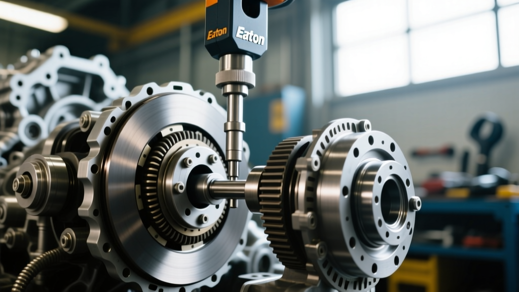
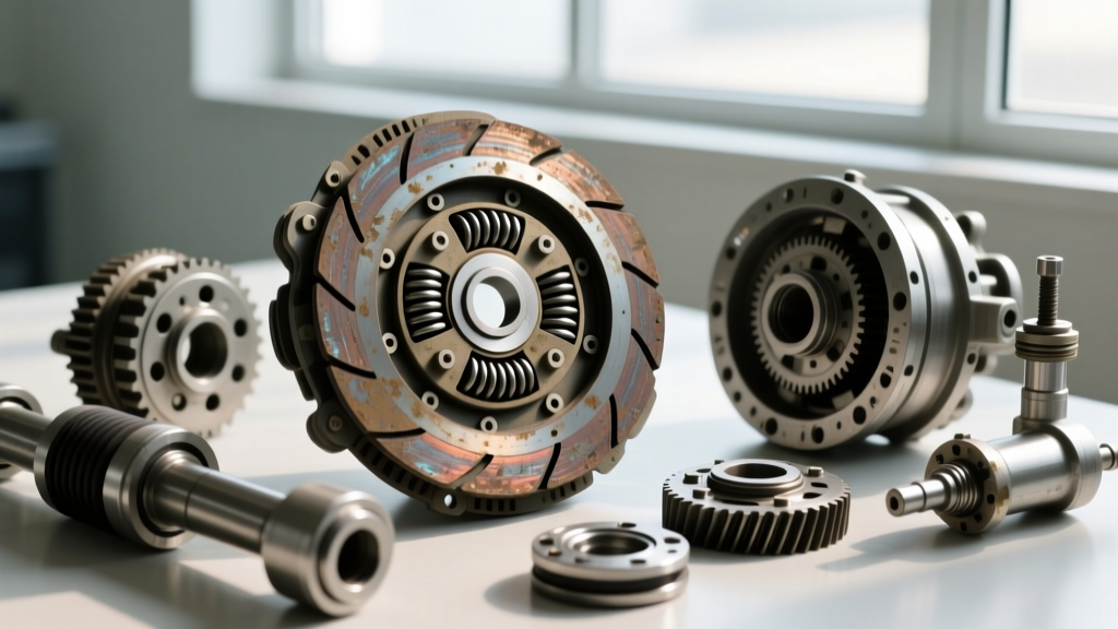
Clutch drag occurs when the friction disc fails to fully disengage from the flywheel or pressure plate, even when the clutch pedal is fully depressed. This symptom manifests as grinding when shifting into first or reverse, vehicle creeping while stationary in gear, and accelerated synchronizer wear inside the transmission. In modern manual powertrains—such as those mated to Tremec T-56 Magnum or Getrag 6-speed gearboxes—release problems are rarely just a 'worn disc.' They are usually a complex interplay of hydraulic stroke limitations, Self-Adjusting Clutch (SAC) mechanism failures, or bellhousing misalignment.
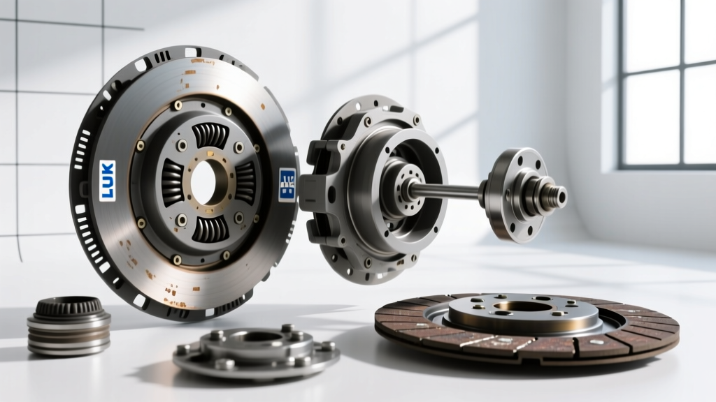
As a senior drivetrain diagnostic technician, I have compiled this step-by-step how-to guide to systematically isolate clutch drag. Furthermore, correctly identifying the exact release system architecture via the LuK clutch catalog online is a mandatory first step before wrenching, as installing the wrong release bearing profile or ignoring SAC reset procedures will guarantee immediate drag upon reassembly.
Step 1: Verify Pedal Freeplay and Hydraulic Stroke
Before pulling the transmission, you must verify that the hydraulic release system is delivering adequate stroke to the clutch fork or Concentric Slave Cylinder (CSC).
Measuring Freeplay and Stroke
- Pedal Freeplay: Measure the distance the pedal travels before feeling resistance from the master cylinder pushrod. Specification is typically 10mm to 15mm (0.39 to 0.59 inches). Excessive freeplay robs the system of the stroke needed to fully disengage the pressure plate diaphragm.
- Slave Cylinder Stroke: Have an assistant depress the clutch pedal while you measure the CSC travel or external fork movement. Most modern CSCs require between 12mm and 18mm of linear travel to achieve full release. If travel is under 10mm, the system is aerated, the master cylinder bypass port is failing, or the CSC is internally bypassing.
- Fluid Verification: Check the reservoir. Modern DOT 4 or DOT 5.1 fluid is highly hygroscopic. Moisture ingress lowers the boiling point, causing vapor lock under heavy stop-and-go traffic, resulting in a spongy pedal and subsequent clutch drag.
When sourcing a replacement CSC, always consult the LuK clutch catalog online to verify the exact stroke length and fluid displacement requirements for your specific VIN. A mismatched CSC (e.g., using a 12mm stroke unit on an application requiring 16mm) will cause chronic drag.
Step 2: Leverage the LuK Clutch Catalog Online for SAC Verification
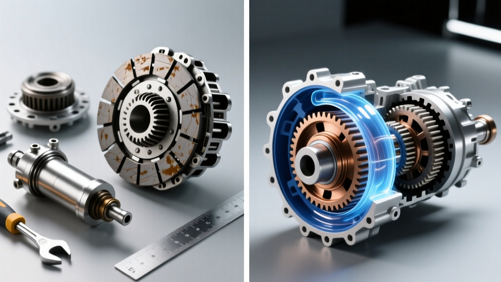
One of the most common causes of clutch drag in European and modern domestic applications is the improper handling of Self-Adjusting Clutches (SAC). LuK pioneered the SAC design to maintain consistent pedal feel and release point as the friction material wears. The SAC features a ramp ring and sensor spring that automatically adjusts the pressure plate's fulcrum point.
The SAC Diagnostic Trap
If a technician removes a worn SAC and attempts to install a new one without using the proper setting tool, or if they mistakenly order a standard diaphragm clutch for a SAC-equipped flywheel, severe clutch drag will occur. The release bearing will bottom out against the SAC ramp ring before the friction disc clears the flywheel.
- Access the LuK clutch catalog online via the RepXpert technical portal.
- Input your exact VIN or OE part number.
- Verify if the application requires a LuK RepSet SAC or a standard RepSet.
- Note the required setting tool part number (e.g., LuK SAC tool kit 400 0072 10). This tool is mandatory to pre-load the SAC mechanism to the factory zero-wear position before torquing the pressure plate to the flywheel.
Skipping the SAC reset tool forces the release bearing to work against the mechanical stop of the adjuster ring rather than the diaphragm spring, resulting in incomplete release and immediate gear clash.
Step 3: Inspect the Release Mechanism and Pivot Geometry
For vehicles utilizing an external release fork and pivot ball (common in rear-wheel-drive applications like the Ford Mustang or Chevrolet Camaro), mechanical wear drastically alters the release ratio.
Pivot Ball and Fork Pad Wear
- Pivot Ball Inspection: Remove the inspection cover and examine the pivot ball. A wear groove deeper than 0.5mm changes the fulcrum geometry, reducing the effective stroke at the release bearing by up to 2mm. Replace the pivot ball and torque to the manufacturer spec (typically 15-20 lb-ft with a drop of blue Loctite).
- Fork Pad Thickness: Measure the fork pads where they contact the release bearing. If wear exceeds 1.0mm, the fork will over-center, causing the bearing to bind on the transmission input shaft retainer collar, preventing full forward travel.
- Retainer Collar Grooving: Inspect the aluminum or steel transmission input shaft bearing retainer. Deep grooves will cause the release bearing to hang up, preventing the clutch from fully engaging or releasing smoothly.
Step 4: Measure Pilot Bearing Runout and Input Shaft Spline Bind
Clutch drag is not always a release system failure; sometimes, the friction disc refuses to slide back on the input shaft splines when the pressure plate releases its clamping force.
Spline and Pilot Bearing Diagnostics
Apply a light coat of high-melting-point synthetic grease (like Lubriplate or specific spline grease provided in premium LuK RepSets) to the input shaft splines. Never pack the splines heavily; excess grease will migrate to the friction surfaces, causing catastrophic slipping once hot.
Next, check the pilot bearing or bushing in the crankshaft flange. A seized pilot bearing will physically drag the input shaft, spinning the transmission gears even when the clutch is fully disengaged. Use a dial indicator to check pilot bearing runout. Maximum allowable runout is typically 0.005 inches (0.12mm). If the bearing is bound or out of spec, the input shaft will deflect, causing the friction disc to bind on the splines and drag against the flywheel.
Step 5: Bellhousing Dowel Alignment
If the transmission bellhousing is misaligned relative to the engine block, the input shaft will sit at an angle to the crankshaft. This angular misalignment forces the friction disc hub to bind laterally against the splines during release, preventing the disc from moving away from the flywheel.
Dowel Pin Runout Measurement
- Mount a magnetic base dial indicator to the crankshaft or flywheel face.
- Position the indicator needle against the inside diameter of the bellhousing dowel pin hole.
- Rotate the crankshaft 360 degrees and record the Total Indicator Runout (TIR).
- Maximum allowable TIR for most performance and passenger vehicles is 0.005 inches (0.12mm). High-performance applications (e.g., Tremec Magnum-F equipped track cars) demand a tighter 0.003 inches (0.07mm).
- If out of spec, install offset dowel pins (available in 0.007, 0.014, and 0.021-inch offsets) to correct the alignment.
Diagnostic Reference Table: Clutch Drag Root Causes
| Symptom Manifestation | Primary Root Cause | Diagnostic Measurement / Spec | LuK Catalog Lookup Focus |
|---|---|---|---|
| Grinding into 1st/Reverse only | Insufficient hydraulic stroke or aerated CSC | CSC travel less than 12mm | Verify CSC part number and fluid volume |
| Creeping at stoplights, hard shifts | SAC mechanism not reset during install | Pedal engagement point at floor | Confirm SAC vs. Standard RepSet requirement |
| Intermittent drag when engine is hot | Vapor lock in hydraulic fluid / Spline bind | Fluid boiling point degraded / Dry splines | Check for updated high-temp CSC revisions |
| Constant drag, input shaft noise | Bellhousing misalignment or pilot bearing failure | Bellhousing TIR > 0.005 inches | Verify pilot bearing OD/ID specs for crank |
| Pedal over-center or mechanical bind | Worn fork pads or grooved retainer collar | Fork pad wear > 1.0mm | Cross-reference release bearing guide sleeve |
Final Torque Specs and Reassembly Protocol
Once the root cause is identified and parts are verified via the catalog, precise reassembly is critical to prevent recurring release problems.
- Flywheel to Crankshaft: Always use new bolts. Typical GM LS applications require 25 lb-ft plus an additional 50 degrees of rotation. Ford Modular V8s often spec 65 lb-ft plus 90 degrees. Always follow the specific OE torque-to-yield sequence.
- Pressure Plate to Flywheel: Torque in a star pattern. Standard M8 bolts typically require 18-22 lb-ft. If installing a LuK SAC, ensure the setting tool is fully engaged and the pressure plate is drawn down evenly to prevent warping the diaphragm spring.
- Bellhousing to Block: Torque to 37-50 lb-ft depending on the fastener size (M10 vs M12), ensuring the dowel pins seat fully without binding.
Clutch drag is a systemic failure that demands a methodical approach. By combining precise mechanical measurements with accurate part identification through the LuK clutch catalog online, you can eliminate release problems, restore crisp gear engagement, and ensure the longevity of the entire manual drivetrain assembly. In 2026, with the increasing complexity of dual-mass flywheels and integrated hydraulic releases, skipping the catalog verification step is a gamble no professional diagnostician should take.