The Architectural Divide: ISS vs. OSS vs. Speedometer
When a driver's speedometer drops to zero, fluctuates wildly, or completely dies, the immediate instinct for both DIYers and general repair technicians is to blame the Vehicle Speed Sensor (VSS) or Output Speed Sensor (OSS). However, in modern powertrain management systems, a failing transmission input speed sensor (ISS) can trigger a cascade of electronic failsafes that completely disable the speedometer. To diagnose transmission speedometer sensor issues accurately, one must first understand the architectural divide between turbine shaft monitoring and vehicle speed calculation.
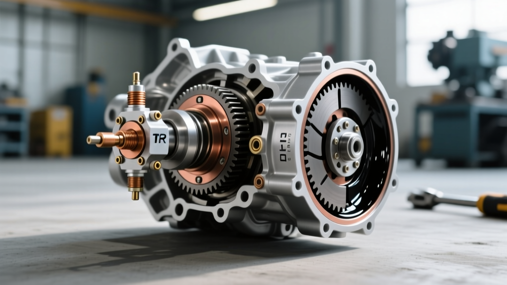
The transmission input speed sensor is mounted deep inside the transmission bell housing or case, positioned to read the reluctor ring on the torque converter turbine shaft. Its primary job is to measure engine power entering the transmission. The TCM (Transmission Control Module) compares this ISS data against the OSS (Output Speed Sensor) data to calculate the exact clutch slip ratio during shifts. The speedometer, conversely, is driven by the OSS, ABS wheel speed sensors, or a dedicated tail-housing VSS. So why does a bad ISS kill the speedometer? The answer lies in network failsafes and limp mode logic.
How an ISS Failure Kills the Speedometer (The Failsafe Cascade)
Modern vehicles do not use hardwired analog signals to drive the instrument cluster speedometer. Instead, the TCM or ABS module calculates vehicle speed and broadcasts it across the CAN (Controller Area Network) bus to the instrument cluster. When the Turbine Speed Sensor Circuit (DTC P0715) fails, or when the TCM detects a rationality error between the ISS and OSS (DTC P0716 or P0717), the module loses its ability to calculate clutch slip.
Without slip ratio data, the TCM cannot safely command PWM (Pulse Width Modulation) shift solenoids. A miscalculated shift could result in engine over-revving (flare) or clutch pack burn-up. To protect the driveline, the TCM immediately commands Limp Mode (Failsafe). During Limp Mode, many OEMs—specifically General Motors, Chrysler, and Ford—intentionally suppress non-essential CAN bus broadcasts or default the instrument cluster speedometer to zero. This is a psychological failsafe designed to force the driver to pull over and seek immediate service. The speedometer hardware is perfectly fine; the signal is being intentionally choked by the TCM.
Expert Diagnostic Tip: If your scan tool shows a valid OSS reading and ABS wheel speeds, but the PID for 'Commanded Vehicle Speed' to the CAN bus is zero while a P0715 or P0717 code is present, your speedometer issue is a secondary symptom of an ISS failure, not a broken speedometer sensor.
Signal Diagnostics: Oscilloscope vs. Multimeter
Relying solely on a multimeter to test a transmission input speed sensor is a recipe for misdiagnosis. While you can check for reference voltage (usually 5V or 12V) and ground continuity, an ohmmeter cannot detect a degraded waveform or a chipped reluctor tooth. A digital storage oscilloscope (DSO) is mandatory for definitive diagnosis.
Automotive speed sensors generally fall into two categories: Variable Reluctance (VR) and Hall-Effect. Knowing which type your transmission uses dictates your diagnostic approach.
| Sensor Type | Waveform | Amplitude | Typical Application |
|---|---|---|---|
| Variable Reluctance (VR) | Sine Wave (AC) | 0.5V to 2.0V+ (RPM dependent) | Older GM 4L60E, Ford 4R70W |
| Hall-Effect | Square Wave (DC) | 0V to 5V / 12V (Constant) | GM 6L80/8L90, ZF 8HP, Ford 6R80 |
| Magnetoresistive (MR) | Square Wave (DC) | 0.75mA to 2.25mA (Current) | Modern ABS & some ZF Mechatronics |
When back-probing a Hall-Effect ISS, you should see a crisp, square waveform that transitions cleanly between 0V and 5V. If the square wave shows 'shark fin' rounding at the peaks or drops out entirely at specific RPMs, you are likely dealing with a failing sensor IC or excessive metallic debris on the magnetic pickup tip, not a wiring issue.
Platform-Specific Quirks and Part Numbers
Diagnosing transmission speedometer sensor issues requires platform-specific knowledge. The era of the $25 screw-in speed sensor is largely over. Here is how the ISS and speedometer architecture behaves on three of the most common modern transmissions.
GM 6L80 / 6L90 (TEHCM Integration)
On GM's 6-speed and 8-speed rear-wheel-drive platforms, the ISS and OSS are not standalone sensors. They are integrated directly into the TEHCM (Transmission Electro-Hydraulic Control Module), which sits inside the transmission pan. If the ISS fails and triggers a speedometer drop-out via CAN bus failsafe, you cannot simply swap a sensor. You must replace the entire TEHCM assembly.
- OEM Part Number: 24253113 (or updated suffix variants)
- Cost: $450 - $850 for the module
- Programming: Requires GM SPS (Service Programming System) to flash the calibration and perform the 'Service Fast Learn' adaptation procedure.
- Torque Spec: TEHCM mounting bolts must be torqued to exactly 11 Nm (97 lb-in) in the specified star pattern to prevent valve body warping.
Ford 6R80 (Molded Lead Frame)
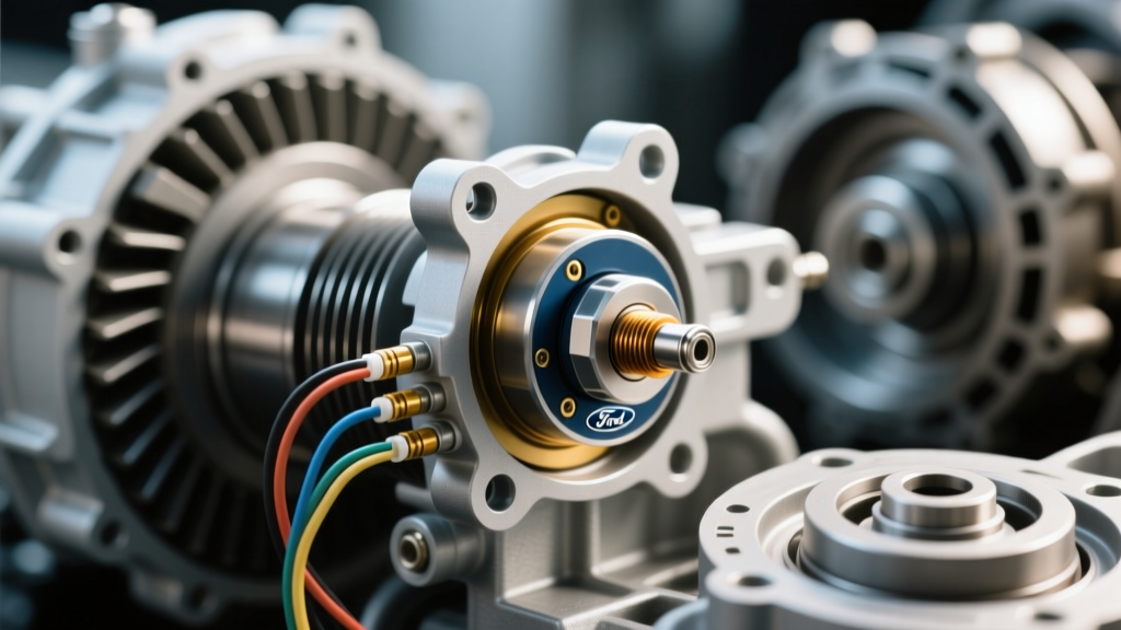
The Ford 6R80 (found in F-150s and Mustangs) utilizes a molded lead frame that houses the ISS, OSS, and temperature sensor. A common failure point is the solder joints cracking due to thermal cycling, causing intermittent ISS drop-outs. This triggers P0715 and forces the truck into limp mode, killing the digital speedometer readout in the instrument cluster.
- OEM Part Number: 7L1Z-7G101-A (Molded Lead Frame)
- Cost: $180 - $250
- Fluid Note: Requires draining and refilling MERCON LV. Level check must be performed with fluid temperature between 185°F and 201°F via the drip plug on the pan.
ZF 8HP (Mechatronic Sleeve)
In the ubiquitous ZF 8HP (used by BMW, Audi, Chrysler, and Ford), the speed sensors are integrated into the Mechatronic unit. However, the wiring passes through a sealing sleeve that is notorious for leaking and wicking fluid into the TCM connector. Before condemning the internal ISS, inspect the external mechatronic sleeve for capillary wicking. Fluid in the connector can short the 5V reference circuit, killing both the ISS signal and the CAN bus speedometer broadcast.
Replacement Procedures: Clearances and Debris
For transmissions that do utilize standalone, bolt-in speed sensors (such as the older GM 4L60E or various Allison heavy-duty units), installation precision is critical. The Sonnax Transmission Tech Resources database frequently highlights sensor air-gap issues as a primary cause of recurring speed sensor codes.
Variable Reluctance sensors require a precise air gap between the sensor tip and the reluctor wheel, typically between 0.5mm and 1.5mm. If you reinstall the sensor without checking the O-ring seating, or if a piece of old O-ring gets trapped under the mounting flange, the air gap increases. The signal amplitude drops, and the TCM loses the ISS reading at higher RPMs, triggering a rationality code that shuts down the speedometer.
Furthermore, because the ISS sits directly in the turbulent fluid flow near the torque converter, it acts as a magnet for clutch material and metallic shavings. Always wipe the sensor tip clean during routine transmission fluid services. A heavy buildup of 'fuzz' on the magnetic tip will distort the sine or square wave, leading to erratic shift timing and intermittent speedometer flutter.
Summary Diagnostic Checklist for Technicians
- Scan for Network Codes: Check for U-codes (CAN bus) alongside P07xx transmission codes. A speedometer drop with a P0715 is a TCM failsafe, not a cluster failure.
- Monitor Live Data PIDs: Compare ISS RPM to Engine RPM at idle in gear. They should be nearly identical (minus slight converter slip). If ISS reads 0 while Engine RPM is 600, the sensor, wiring, or TEHCM is dead.
- Scope the Signal: Back-probe the sensor at the TCM connector to rule out internal transmission wiring harness chafing (a common issue where the harness rubs against the valve body casting).
- Inspect for Wicking: On ZF and Chrysler units, check the external connector for ATF contamination before authorizing a transmission teardown.
Understanding the symbiotic relationship between the transmission input speed sensor, the TCM's failsafe logic, and the CAN bus network is the key to accurately resolving modern speedometer anomalies. Stop chasing phantom VSS ghosts and start analyzing the slip-ratio data that dictates your vehicle's electronic survival.