The Tribology and Mechanics of Clutch Slip
When a driver reports that their clutch slipped, it is rarely a singular, isolated point of failure. From an engineering perspective, clutch slip is the culmination of degraded tribological friction coefficients, compromised hydraulic clamping force, or severe thermal runaway. Diagnosing the root cause requires moving beyond basic pedal adjustments and executing a comprehensive, measurement-driven inspection checklist. Whether you are dealing with a high-torque Tremec T56 Magnum in a performance application or a Ford MT-82 in a daily driver, understanding the exact tolerances and failure modes is critical for a permanent repair.
This technical deep-dive provides the definitive inspection protocol for automotive technicians and advanced DIYers to isolate friction loss, hydraulic bypass, and mechanical interference.
Phase 1: Hydraulic & Pedal Geometry Verification
Before dropping the transmission, the hydraulic actuation system must be verified. A common misdiagnosis of a 'slipping' clutch is actually a clutch that is never fully engaging due to hydraulic pre-load.
Master Cylinder Pushrod Clearance
Hydraulic clutch systems require a specific amount of free play at the master cylinder pushrod to allow the internal fluid return port to open. If the pushrod is adjusted too tightly (zero clearance), the master cylinder piston remains slightly depressed. This traps fluid pressure in the line, keeping the release bearing partially engaged against the diaphragm spring, effectively reducing clamping force and causing the clutch to slip under load.
- Specification: Verify 0.050" to 0.100" of free play at the master cylinder pushrod before piston engagement.
- Fluid Integrity: Test DOT 3/DOT 4 fluid for moisture contamination. Fluid with >3% water content lowers the boiling point, leading to vapor lock and inconsistent pedal feel under heavy thermal loads.
Slave Cylinder Travel & Bypass Testing
For internal concentric slave cylinders (CSC), such as those found in GM LS/LT applications, internal seal bypass can mimic a slipping clutch. If the CSC piston seals are worn, high line pressure bleeds past the piston during heavy pedal application, resulting in incomplete disengagement or erratic engagement points. Bench-bleeding the CSC prior to installation is mandatory to prevent trapped air from acting as a compressible spring.
Phase 2: External Linkage & Release Mechanism
With the transmission removed, the external linkage and release collar must be inspected for mechanical binding and wear patterns that rob clamping force.
Fork Pivot Ball & Release Bearing Wear
Inspect the clutch fork pivot ball stud for asymmetric wear. In high-torque applications, the fork can flex, altering the geometry of the release bearing's travel.
Technical Note: When reinstalling the clutch fork pivot ball stud on a GM T56/T56 Magnum bell housing, the factory torque specification is 28 lb-ft. Apply a medium-strength threadlocker (e.g., Loctite 242) to prevent backing out, which would instantly alter the clutch engagement point and induce slip.
Examine the release bearing collar (the sleeve it rides on). If the collar has worn a groove deeper than 0.020", the bearing will not travel the full required distance, leading to incomplete pressure plate actuation and premature friction disc wear.
Phase 3: Bell Housing & Internal Component Teardown
This phase requires precision measuring tools. Guesswork here leads to repeat failures and warranty denials.
Flywheel Runout & Surface Topography
Flywheel runout is a primary culprit for localized clutch slip and severe chatter. Mount a magnetic dial indicator to the engine block and measure the flywheel face.
- OEM Tolerance: Maximum Total Indicated Runout (TIR) is typically 0.005" (0.127mm).
- Corrective Action: If runout exceeds 0.005", the flywheel must be resurfaced on a precision brake lathe or replaced. Never use shims behind the flywheel to correct crankshaft flange runout.
Pressure Plate Diaphragm Spring Fingers
The diaphragm spring provides the clamping load (often exceeding 2,500 lbs of force in performance applications). Inspect the tips of the diaphragm fingers where the release bearing makes contact. If the fingers exhibit wear grooves deeper than 0.030", the effective clamping load is drastically reduced because the spring's leverage ratio is altered. The pressure plate assembly must be replaced; it is not a serviceable component.
Friction Disc Thickness & Marcel Spring Compression
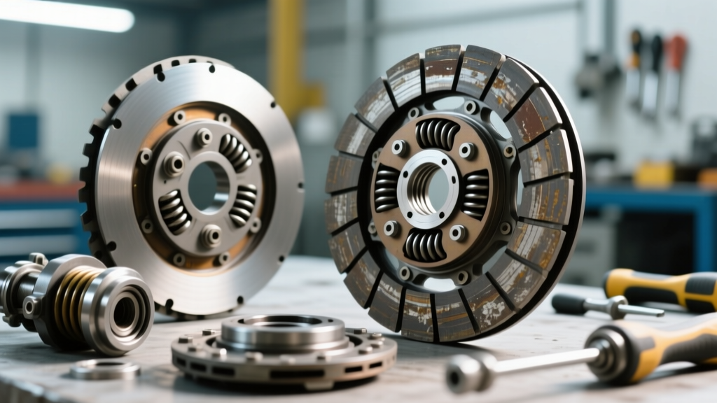
Measure the friction disc thickness at the thinnest point. Compare this against the manufacturer's minimum discard thickness (usually stamped on the hub or available in service data). Furthermore, inspect the 'marcel' springs (the wave springs between the friction facings). These springs compress to provide smooth engagement. If they are crushed flat or heat-blued, the clutch will engage abruptly, causing driveline shock and subsequent micro-slippage as the drivetrain bounces.
Phase 4: Inspection Tolerance Matrix
Use the following data table as a quick-reference guide during your teardown inspection to determine if components are within serviceable limits.
| Component | Measurement Parameter | OEM Tolerance Limit | Failure Consequence |
|---|---|---|---|
| Flywheel Face | Total Indicated Runout (TIR) | < 0.005" (0.127mm) | Chatter, localized slip, premature wear |
| Diaphragm Fingers | Wear Groove Depth | < 0.030" (0.76mm) | Reduced clamping force, heavy slip |
| Friction Disc | Thickness to Hub Flange | > 0.040" above hub | Hub contact, catastrophic failure |
| Slave Cylinder | Pushrod Travel | Per OEM (e.g., 0.600") | Incomplete disengagement/engagement |
| Flywheel Bolts | Stretch / Torque-to-Yield | No visible necking | Bolt failure, flywheel detachment |
Phase 5: Contamination & Thermal Forensics
A clutch that has slipped will leave distinct forensic evidence on the friction material. Identifying the type of thermal damage or contamination dictates the next steps in the repair.
Oil Ingress: Rear Main Seal vs. Input Shaft Seal
Oil on the friction disc destroys the coefficient of friction ($\mu$), causing immediate and severe slip. You must identify the source of the hydrocarbon contamination:
- Engine Oil (e.g., 5W-30): Indicates a failed crankshaft rear main seal (RMS) or a porous engine block casting. Requires engine-side repair.
- Gear Oil / ATF (e.g., 75W-90 or Dexron VI): Indicates a failed transmission input shaft seal. Requires transmission-side repair.
Critical Step: If the flywheel is contaminated with oil, it must be chemically cleaned or replaced. Cast iron is porous; simply wiping it down will result in oil weeping back onto the new clutch disc upon first heat cycle.
Glazing vs. Charring
Glazing occurs when the clutch is 'ridden' at low RPM, generating just enough heat to melt the resins in the organic friction material, creating a glass-like, low-friction surface. Glazed discs cannot be sanded and reused; the structural integrity of the friction matrix is compromised.
Charring (black, flaky, burnt material) indicates extreme thermal runaway, usually from aggressive launch control or heavy towing beyond the clutch's torque capacity (e.g., exceeding the 450 lb-ft limit of a standard organic disc in a modified diesel application). In these cases, an upgrade to a cerametallic or Kevlar-based friction material (such as those offered by Exedy or Mantic) is required to handle the elevated thermal thresholds.
Dual-Mass Flywheel (DMF) Diagnostic Protocols
If the vehicle is equipped with a Dual-Mass Flywheel (common in modern diesel and high-torque manual applications like the Ford 6.7L PowerStroke or BMW ZF 6-speed setups), internal spring failure can cause symptoms that mimic a slipping clutch. The DMF contains internal torsional dampening springs. To test a DMF on the bench:
- Lock the primary mass (engine side) and rotate the secondary mass (transmission side).
- Measure the free-play arc rotation. Most OEM DMFs (e.g., LUK or Sachs) allow between 20 to 35 degrees of free rotation before the internal springs engage.
- If the secondary mass rotates freely with no spring resistance, or if it exhibits metallic clunking and binds, the internal dampeners have collapsed. The DMF must be replaced. Never attempt to resurface a DMF; the heat from machining will destroy the internal grease and bearings.
Fastener Torque Specifications & Assembly
When reassembling the drivetrain, adhering to exact torque specifications is non-negotiable to prevent runout and subsequent slip. Always use new, OEM-style or high-grade aftermarket fasteners.
- GM LS/LT Engines (M10x1.5 Flywheel Bolts): OEM Torque-to-Yield (TTY) requires 74 lb-ft + 90 degrees. If using aftermarket ARP 200-2802 bolts, torque to 95 lb-ft using ARP Ultra-Torque lube.
- Ford Modular/Coyote (M12 Flywheel Bolts): OEM TTY requires 59 lb-ft + 90 degrees. ARP equivalents are typically torqued to 110 lb-ft.
- Pressure Plate to Flywheel: Typically 25-35 lb-ft (depending on thread size, usually M8). Always tighten in a star pattern, incrementally increasing torque by 5 lb-ft per pass to ensure the pressure plate housing does not warp, which would induce immediate slip and chatter.
Summary: The Engineering Approach to Drivetrain Diagnostics
Concluding that a 'clutch slipped' is merely the starting point of the diagnostic process. By systematically verifying hydraulic geometry, measuring flywheel runout with precision instruments, analyzing friction material forensics, and adhering to strict torque specifications, technicians can eliminate the root cause of the failure. For further reading on clutch tribology and drivetrain engineering standards, refer to the SAE International Technical Papers database, and always consult model-specific Tremec Service Documentation when working with high-performance manual transmissions.