The Kinematics of Friction Wear: Pedal Geometry as a Measuring Tool
Most drivers view the clutch pedal as a simple on/off switch. As transmission specialists, we view it as a linear potentiometer measuring friction material thickness. When assessing clutch wear signs and lifespan indicators, performing a precise clutch pedal adjustment and measurement protocol is vastly more accurate than simply 'feeling' for slip under heavy load. A standard 9.5mm organic friction disc wears down to the rivet depth at roughly 6.0mm, yielding exactly 3.5mm of usable material. With a typical release fork ratio of 1.8:1, the slave cylinder must travel an additional 6.3mm over the lifespan of the clutch to maintain engagement. In a hydraulic system utilizing a 5/8-inch master cylinder and a 7/8-inch slave cylinder, the hydraulic area ratio is 0.64. This mathematical reality dictates that the pedal must travel an extra 10mm to 12mm at the end of its life just to compensate for physical wear.
Why Clutch Pedal Adjustment is a Diagnostic Baseline
Before diagnosing slip, chatter, or engagement issues, establishing a baseline via clutch pedal adjustment is mandatory. Modern hydraulic systems often utilize self-adjusting master cylinders with internal bypass ports, leading many technicians to believe pedal geometry is fixed. This is a critical error. According to McLeod Racing's technical documentation, improper pushrod preload on self-adjusting masters is a leading cause of premature throwout bearing failure and diaphragm spring fatigue.
If a mechanic incorrectly performs a clutch pedal adjustment by eliminating all free play to 'raise the bite point' for a worn disc, the master cylinder's internal compensation port remains blocked. As the hydraulic fluid heats up and expands, it acts as a solid column, effectively riding the clutch and causing catastrophic slip. True diagnostic measurement requires verifying the physical gap between the master cylinder pushrod and the piston cup, which should typically measure between 0.020 and 0.040 inches (0.5mm - 1.0mm) of clearance.
Platform-Specific Pedal Geometry & Free Play Data
Clutch wear signs manifest differently depending on the transmission architecture and hydraulic ratio. Below is a diagnostic reference table for common modern manual platforms. Deviations from these specifications during a clutch pedal adjustment procedure are primary indicators of remaining friction material lifespan.
| Vehicle Platform | Transmission Model | Master / Slave Bore | Spec Free Play | Max Slave Stroke (Wear Limit) |
|---|---|---|---|---|
| Honda Civic Type R (K20C1) | 6-Speed Manual | 5/8" / 3/4" | 0.39 - 0.59 in | 16.5 mm |
| Ford Mustang GT (5.0L Coyote) | Getrag MT-82 | 5/8" / 7/8" | 0.78 - 1.18 in | 18.0 mm |
| Chevrolet Corvette C7 (LT1) | Tremec TR-6070 | 3/4" / Hydraulic TOB | Self-Adjusting | 12.0 mm (TOB Extension) |
| Subaru WRX (FA20DIT) | 6-Speed (TY85) | 5/8" / 7/8" | 0.20 - 0.40 in | 15.5 mm |
Verifying Hydraulic Pushrod Preload
On platforms like the Honda K-Series or Subaru FA20, the under-dash pushrod is threaded and secured with a 12mm locknut. To accurately read clutch wear signs, loosen the locknut and back the pushrod out until it completely clears the master cylinder piston. Slowly thread the pushrod back in until you feel resistance—this is the piston resting against the internal snap ring. Back the pushrod out exactly one-half to one full turn to establish the necessary fluid return clearance. If the pedal previously required massive free play to achieve this state, the friction disc is nearing the end of its service life.
Slave Cylinder Stroke: The Ultimate Lifespan Indicator
While pedal free play indicates hydraulic system health, measuring slave cylinder stroke provides the raw data on friction disc thickness. As detailed in Exedy USA's technical guides, measuring the physical displacement of the release fork is the most definitive way to calculate remaining lifespan without dropping the transmission.
- Preparation: Secure the vehicle on a lift and remove the transmission dust cover or slave cylinder inspection plug.
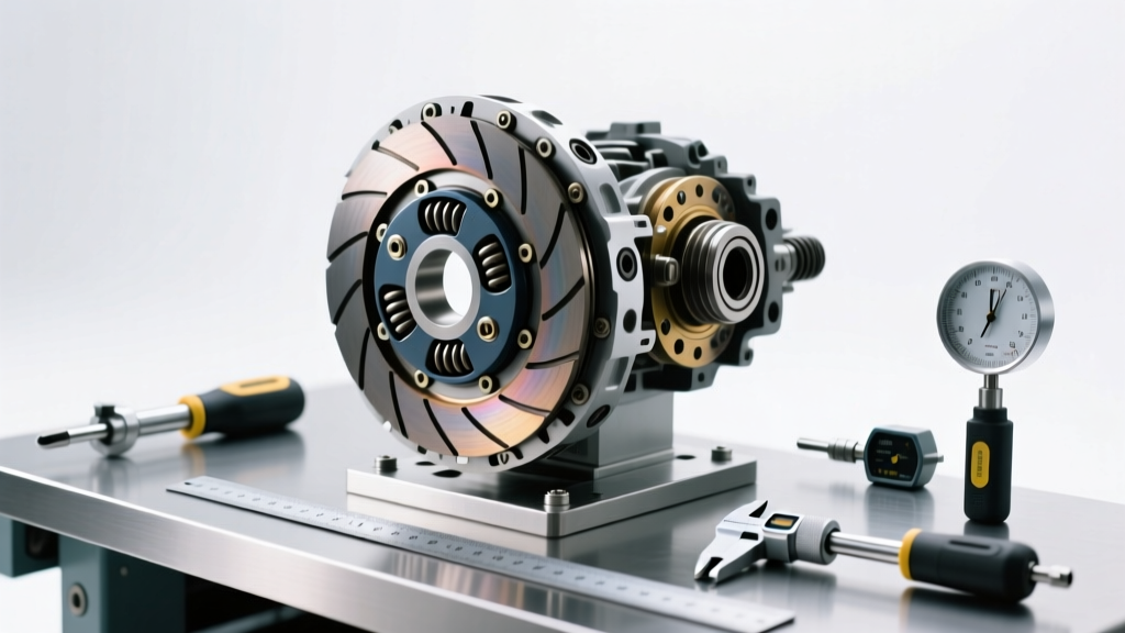
- Tooling: Mount a magnetic dial indicator against the transmission bellhousing, with the plunger resting squarely on the slave cylinder pushrod or release fork pivot.
- Measurement: Have an assistant fully depress the clutch pedal. Record the total travel.
- Analysis: Compare the reading to the manufacturer's maximum stroke limit (see table above). If a Getrag MT-82 slave cylinder is pushing 17.5mm of stroke, the diaphragm spring fingers are being pushed past their optimal operating plane. The clutch is not slipping yet, but the wear signs are mathematically confirmed: replacement is required within 3,000 to 5,000 miles.
Advanced Diagnostics: Internal Hydraulic Throwout Bearings (IHTOB)
Vehicles equipped with Tremec T56 Magnum or TR-6070 transmissions often utilize an Internal Hydraulic Throwout Bearing (IHTOB) instead of an external fork and slave setup. Diagnosing wear on these systems requires a different approach to clutch pedal adjustment. Because the IHTOB rides constantly against the diaphragm spring fingers, there is zero mechanical free play. Instead, wear signs are diagnosed by measuring the fluid volume required to actuate the system.
By installing an inline hydraulic pressure transducer and a pedal position sensor, specialists can map the pressure-to-travel curve. As the friction disc wears and the diaphragm spring fingers move outward toward the transmission, the IHTOB piston must extend further. If the piston extends beyond its designed 12mm to 14mm maximum stroke, the internal O-rings begin to ride on the unpolished portion of the bore, leading to rapid fluid bypass and sudden pedal drop. Centerforce recommends bleeding these systems using a minimum of 40 PSI of regulated air pressure to ensure zero micro-bubbles, which can falsely alter pedal travel diagnostics.
The Financial Impact of Ignoring Pedal Geometry
Ignoring the data provided by clutch pedal adjustment and bite point migration leads to cascading, expensive failures. When a friction disc wears past the 6.0mm threshold, the rivets begin to score the flywheel friction surface.
- OEM Replacement Costs: A standard LuK RepSet (e.g., Part # 04-165 for Honda applications) costs between $250 and $350. However, if the dual-mass flywheel (DMF) is scored, the DMF replacement (e.g., LuK 415022009) adds $800 to $1,200 to the parts bill alone.
- Single-Mass Conversions: To avoid future DMF costs, many opt for a Single-Mass Flywheel (SMFW) conversion kit from Exedy or ACT. While this saves $600 upfront, it introduces gear rattle and requires careful clutch pedal adjustment to manage the harsher engagement characteristics of a solid hub disc.
- Throwout Bearing Collar Wear: If a hydraulic system is forced to over-stroke to compensate for a worn disc, the throwout bearing collar can machine a groove into the transmission input shaft sleeve. Repairing a scored input shaft requires a complete transmission teardown, pushing labor costs past $1,500.
Conclusion: Data Over Sensation
Relying on the 'feel' of the clutch pedal is an outdated diagnostic method. By treating clutch pedal adjustment as a precise metrology exercise, technicians and enthusiasts can accurately map friction material wear, predict failure timelines, and avoid catastrophic damage to the flywheel and transmission input shaft. Measure the free play, calculate the hydraulic ratio, and let the dial indicator dictate your maintenance schedule.