The Critical Role of Hydraulic Clutch Maintenance
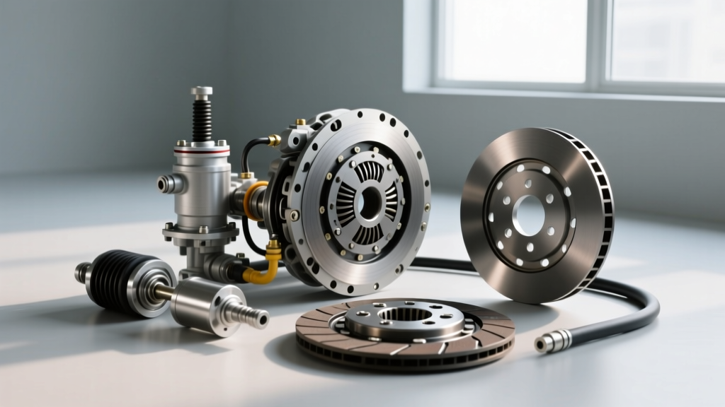
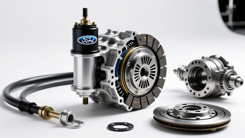
In the modern automotive landscape, the mechanical linkages and cable-driven actuators of the past have been entirely superseded by hydraulic actuation. Whether you are driving a track-focused vehicle equipped with a Tremec T56 Magnum or a daily driver utilizing a modern automated manual transmission (AMT), the hydraulic circuit is the vital bridge between driver intent and mechanical engagement. However, because the clutch hydraulic system shares design DNA—and often the same fluid reservoir—with the brake system, it is frequently overlooked during routine maintenance. When evaluating the complete clutch master slave cylinder circuit, proactive maintenance is not just about preserving pedal feel; it is about preventing catastrophic internal seal degradation, release bearing starvation, and premature friction material wear.
This technical deep-dive explores the engineering realities of clutch hydraulic system maintenance, from fluid hygroscopy and seal metallurgy to precision bleeding protocols and pushrod geometry adjustments.
The Hygroscopic Reality: Fluid Degradation and DOT Standards
The most common point of failure in any hydraulic clutch system is not mechanical wear, but fluid degradation. Glycol-based brake and clutch fluids (DOT 3, DOT 4, and DOT 5.1) are inherently hygroscopic, meaning they actively absorb moisture from the atmosphere through microscopic pores in rubber hoses, reservoir caps, and seal boundaries.
As water content increases, the fluid's boiling point plummets, and its corrosive properties accelerate. In a clutch circuit, moisture leads to internal pitting of the master cylinder bore and the swelling of EPDM (Ethylene Propylene Diene Monomer) rubber seals. This swelling increases friction against the bore, resulting in a sluggish pedal return and eventual bypass failure.
According to the SAE J1703 standard governing motor vehicle brake and clutch fluids, maintaining specific wet and dry boiling points is critical for system integrity. While clutch systems do not experience the extreme thermal spikes of brake calipers, the ambient heat transferred from the transmission bell housing to the slave cylinder can easily boil moisture-contaminated fluid, causing vapor lock and a sudden loss of clutch disengagement.
DOT Fluid Specifications and Service Intervals
| Fluid Type | Dry Boiling Point (Min) | Wet Boiling Point (Min) | Recommended Service Interval |
|---|---|---|---|
| DOT 3 | 205°C (401°F) | 140°C (284°F) | Every 2 Years / 30,000 Miles |
| DOT 4 (Standard) | 230°C (446°F) | 155°C (311°F) | Every 2-3 Years / 40,000 Miles |
| DOT 4 (High-Performance) | 300°C+ (572°F+) | 200°C+ (392°F+) | Annually (Track/Heavy Duty Use) |
| DOT 5.1 | 260°C (500°F) | 180°C (356°F) | Every 2 Years / 40,000 Miles |
Note: DOT 5 (Silicone-based) is hydrophobic and must never be used in systems designed for glycol-based fluids, as it will destroy OEM EPDM seals and cannot be mixed without causing a gelatinous blockage in the hydraulic lines.
For optimal maintenance, flushing the system with a high-quality synthetic DOT 4 fluid, such as those meeting ATE SL.6 or TYP 200 specifications, provides superior corrosion inhibitors and lower viscosity, ensuring rapid hydraulic response in cold climates.
Internal Anatomy and Failure Modes of the Clutch Master Slave Cylinder
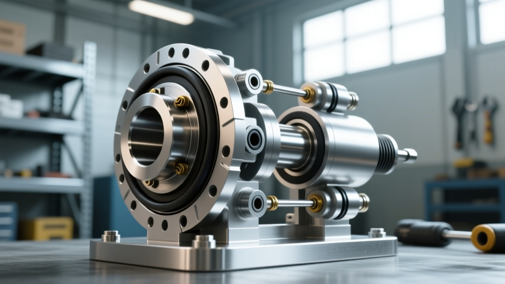
The hydraulic circuit consists of the master cylinder (usually firewall-mounted), the hard/soft hydraulic lines, and the slave cylinder. Slave cylinders are broadly categorized into two types: External Slave Cylinders and Concentric Slave Cylinders (CSC), also known as hydraulic throw-out bearings.
External Slave Cylinders
Found on platforms like the Jeep AX15 or older Honda K-Series transmissions, external slaves utilize a pushrod to actuate a mechanical release fork. Maintenance Insight: The pivot ball and fork contact pad must be lubricated with high-melting-point molybdenum grease during any slave cylinder replacement. Failure to do so causes lateral wear on the slave cylinder pushrod, leading to binding and off-center bore wear.
Concentric Slave Cylinders (CSC)
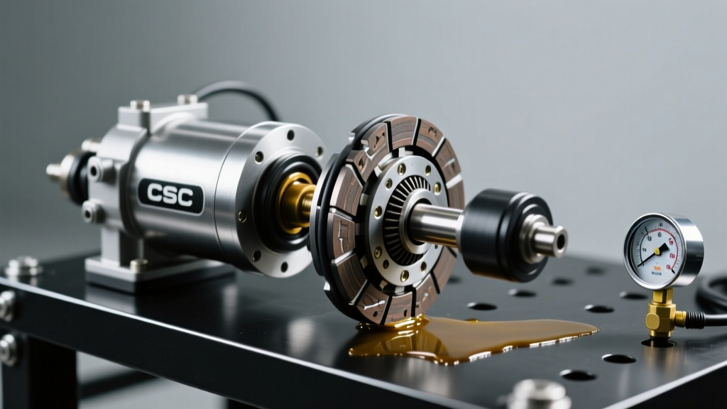
Modern performance and passenger vehicles (e.g., GM Alpha platform, Ford Mustang MT-82, Porsche PDK manual conversions) utilize a CSC that rides directly on the transmission input shaft. While this eliminates mechanical pivot wear and improves pedal modulation, it introduces severe maintenance complexities.
- Failure Mode - Thermal Degradation: CSCs are positioned millimeters from the clutch friction disc. During aggressive driving or stop-and-go traffic, radiant heat bakes the internal seals. As of 2026, OEM CSCs utilizing advanced Viton or high-temp EPDM compounds cost between $180 and $350, but labor requires a full transmission removal ($600–$1,200).
- Failure Mode - Fluid Weeping: A weeping CSC will contaminate the clutch disc with glycol fluid, destroying the friction material. If you notice a dropping fluid level with no visible external leaks on the firewall, the CSC is likely leaking internally into the bell housing.
Precision Bleeding Protocols: Beyond the "Pump and Hold"
The traditional "pump and hold" manual bleeding method is notoriously ineffective for modern clutch hydraulic systems. Clutch lines often route upward from the slave cylinder to the master cylinder, creating natural air traps at high points in the hard lines or quick-connect fittings.
The Reverse-Bleeding Advantage
Because air naturally rises, reverse bleeding is the most technically sound method for clutch circuits. By attaching a syringe or reverse-bleeder tool to the slave cylinder bleeder valve and pushing fresh, degassed fluid upward into the master cylinder reservoir, you force air bubbles to follow their natural buoyancy.
- Extract all old fluid from the master cylinder reservoir using a turkey baster or fluid evacuator.
- Attach a clear hose to the slave bleeder valve and connect a large syringe filled with fresh DOT 4 fluid.
- Open the bleeder valve (typically 8mm or 10mm hex) and slowly inject fluid upward.
- Monitor the master cylinder reservoir to ensure it does not overflow, capping it once fresh, bubble-free fluid emerges.
- Torque Specification: Close the bleeder valve to exactly 8–12 Nm. Bleeder screws are often made of soft brass or plated steel; overtightening will strip the threads or snap the screw head.
Pressure Bleeding and Quick-Connect Lines
For vehicles equipped with hydraulic quick-connect lines (common on Ford and GM trucks), a pressure bleeder set to 15–20 PSI is required to maintain enough system pressure to keep the internal check valves open during the bleed process. Never exceed 30 PSI, as this can blow out the master cylinder piston seals or rupture aging rubber flex hoses.
Diagnostic Pressure Testing and Pushrod Geometry
A spongy pedal is not always the result of air in the lines; it is frequently a symptom of improper pushrod geometry or master cylinder bypass.
Master Cylinder Pushrod Free-Play
The pushrod connecting the clutch pedal to the master cylinder piston must have a specific amount of free-play, typically between 0.5mm and 1.5mm. This microscopic gap ensures that when the pedal is released, the master cylinder piston fully retracts, uncovering the compensation port.
Expert Warning: If an aftermarket adjustable pushrod is set too long, or if the pedal stop is misadjusted, the piston will rest over the compensation port. As the engine bay heats up, the trapped hydraulic fluid expands. With nowhere to go, the pressure will partially engage the slave cylinder, causing the clutch to slip, overheat, and ultimately destroy the friction disc and flywheel.
Always verify pushrod free-play with a feeler gauge between the pushrod tip and the piston depression before securing the master cylinder to the firewall. Firewall mounting nuts should be torqued to 15–22 Nm to prevent firewall flex, which robs the pedal of mechanical leverage and creates a false "spongy" feel.
Line Inspections and Hardware Replacement
Hydraulic lines are the veins of the system. OEM rubber flex hoses are prone to internal delamination, where the inner liner collapses, acting as a one-way check valve. This results in a clutch that engages but fails to disengage, or a pedal that stays on the floor.
During routine maintenance, inspect the hard lines for zinc-flake coating degradation and surface rust. When replacing hard lines, always use a flare nut wrench (line wrench) to remove the fittings. Standard open-end wrenches will round the soft steel nuts. Torque hard line flare nuts to 12–16 Nm. If upgrading to stainless steel braided clutch lines, ensure the banjo bolts or adapter fittings utilize new crush washers and are torqued to the manufacturer's exact specification (usually 20–25 Nm for banjo bolts) to prevent high-pressure weeping.
Summary: The 2026 Maintenance Standard
Maintaining the clutch hydraulic system requires moving beyond simple fluid top-offs. By adhering to strict fluid exchange intervals based on SAE hygroscopic standards, utilizing reverse-bleeding techniques to eliminate vapor traps, and meticulously verifying pushrod geometry, you ensure crisp, reliable engagement. Whether you are preserving a classic manual or maintaining a modern high-torque AMT, treating the clutch master slave cylinder assembly with the same precision as the braking system is the hallmark of true automotive expertise.