The Benchmark of Pedal Feel: Sim Racing vs. Real-World Hydraulics
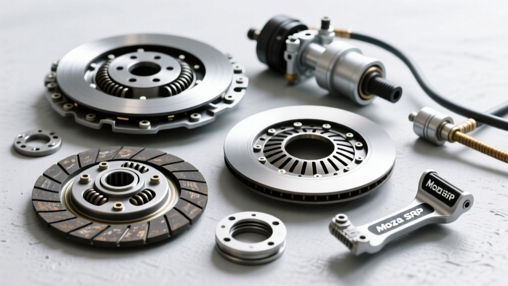
As we navigate the 2026 automotive landscape, the line between high-fidelity simulated training tools and real-world mechanical diagnostics continues to blur. Sim racers and professional drivers alike rely on advanced hardware like the Moza SRP clutch pedal to replicate the exact hydraulic bite points, elastomer deflection, and load-cell feedback of a performance vehicle. The Moza SRP utilizes a 200kg load cell and adjustable bite-point mechanisms to mimic the progressive engagement of a real-world pressure plate. However, when a physical vehicle enters the service bay experiencing clutch slip, chatter, or engagement faults, simulated feel must be replaced by a rigorous, data-driven clutch system inspection checklist.
Diagnosing manual transmission drivetrains—whether it is a classic Porsche G50, a Ford ZF S5-42, or a modern GM Tremec T56 Magnum—requires understanding the physics of hydraulic pressure, mechanical leverage, and friction material degradation. This technical deep-dive explainer bridges the gap between the benchmark pedal feel of advanced simulators and the mechanical realities of real-world clutch system diagnostics.
Phase 1: Hydraulic Master and Slave Cylinder Inspection
The hydraulic clutch system is a closed-loop network that translates foot pressure into mechanical displacement. Unlike the hall-effect sensors in a sim pedal, real-world hydraulics rely on incompressible fluid dynamics. A failure in this system typically manifests as a spongy pedal, failure to disengage (gear crunch), or a pedal that sinks to the floor.
Fluid Dynamics and Seal Degradation
Begin the inspection at the master cylinder. Most OE applications utilize a 5/8-inch or 3/4-inch bore master cylinder. Check the fluid condition; DOT 4 fluid has a dry boiling point of 446°F (230°C), but it is highly hygroscopic. If the fluid appears dark or murky, moisture contamination has occurred, lowering the boiling point and causing vapor lock under heavy track use. Inspect the master cylinder pushrod for exactly 1/16-inch (1.5mm) of free play. If the pushrod is preloaded against the internal piston, it blocks the fluid return port. This causes the system to build residual pressure as the fluid heats up, leading to the clutch slipping under load—a symptom often misdiagnosed as a worn friction disc.
Measuring Slave Cylinder Travel
According to Tremec's engineering documentation for the T56 Magnum, minimum slave cylinder travel is critical for full clutch disengagement. For external slave setups, you must measure the physical throw of the slave pushrod. The required travel is typically between 0.450-inch and 0.550-inch. If travel is insufficient, the release bearing cannot fully compress the pressure plate diaphragm springs, resulting in clutch drag and synchro wear during shifts. For Concentric Slave Cylinders (CSC) found in many modern GM and European applications, internal travel is verified via hydraulic volume displacement or specialized depth gauges during bellhousing removal.
Phase 2: Mechanical Linkage and Release Bearing Assessment
Once hydraulic integrity is confirmed, the inspection moves to the mechanical linkage. This is where the raw, unfiltered mechanical feedback originates—the exact feedback that high-end sim pedals attempt to replicate via elastomer stacks.
Fork Pivot and Throwout Bearing Preload
With the transmission removed, inspect the clutch fork and pivot ball. The pivot ball is a high-wear item; steel balls often develop grooves or flat spots, while titanium upgrades can gall if not properly lubricated with high-melt-point synthetic grease. A worn pivot ball alters the fulcrum ratio, changing the pedal effort and reducing effective slave travel. Torque the pivot ball mounting stud to the manufacturer's specification (typically 20-25 lb-ft for most GM bellhousings) using a medium-strength threadlocker.
Next, evaluate the release bearing (throwout bearing). For hydraulic setups, the bearing should feature a continuous-contact face designed to ride against the diaphragm spring fingers at all times. Inspect the bearing face for asymmetrical wear patterns. A scalloped or uneven wear ring indicates a misaligned bellhousing or a warped pressure plate diaphragm, which will introduce severe high-frequency vibration (chatter) upon engagement.
Diagnostic Matrix: Pedal Symptoms vs. Mechanical Faults
Use the following diagnostic table to correlate pedal feedback anomalies with specific mechanical failures. While a Moza SRP clutch pedal allows you to tune out these faults via software, real-world mechanics must identify the physical root cause.
| Pedal Symptom | Probable Root Cause | Inspection / Correction Protocol |
|---|---|---|
| Spongy / Soft Engagement | Air in hydraulic lines or degraded master cylinder seals | Reverse-bleed system; inspect master bore for scoring; replace DOT 4/5.1 fluid. |
| Hard / Heavy Pedal Effort | Binding fork pivot, dried release bearing collar, or aftermarket high-clamp pressure plate | Lubricate pivot ball and transmission input shaft splines with high-temp moly grease. |
| Pedal Vibration (Chatter) | Oil contamination on friction disc, warped flywheel, or collapsed marcel springs | Measure flywheel runout; inspect for rear main seal leaks; replace clutch assembly. |
| Gear Crunch on Upshifts | Insufficient slave cylinder travel or internal bypass leak | Measure slave throw (min 0.450"); bench-bleed master cylinder; check for line swelling. |
| Pedal Sinking to Floor | Blown slave cylinder seal or braided line failure | Pressure test hydraulic system at 800 PSI; inspect CSC for fluid weeping inside bellhousing. |
Phase 3: Friction Material and Flywheel Runout
The core of the clutch assembly dictates the ultimate engagement feel. Schaeffler's LuK clutch system guidelines emphasize that replacing the friction components without verifying the mating surfaces is the leading cause of premature warranty claims.
Marcel Spring Deflection and Flywheel Tolerances
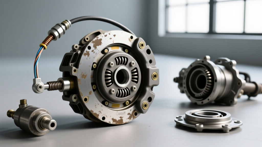
Examine the clutch disc's marcel springs—the wavy steel segments sandwiched between the friction pucks. These springs provide the progressive engagement that separates a smooth, drivable street clutch from an aggressive, on/off race clutch. If the marcel springs are crushed flat due to aggressive riding or excessive heat, the pedal will feel binary, and the vehicle will suffer from low-RPM chatter.
Flywheel runout is the next critical measurement. Using a magnetic-base dial indicator mounted to the engine block, measure the flywheel face runout. The maximum allowable runout for most performance applications is 0.005-inch (0.127mm). Exceeding this tolerance causes the release bearing to pulse against the diaphragm fingers, transmitting a rhythmic vibration directly to the driver's foot. If the vehicle utilizes a Dual Mass Flywheel (DMF), check for excessive rotational free-play (typically limited to 1-2 teeth of the internal gear) and listen for internal spring rattle at idle. In 2026, a quality DMF replacement ranges from $450 to $850, making accurate diagnosis essential before ordering parts.
Advanced Hydraulic Bleeding Protocols
If the inspection checklist reveals air ingress or a component replacement, standard gravity bleeding is rarely sufficient for complex hydraulic clutch lines, especially those with inverted loops or remote slave cylinders. Utilize a reverse-bleeding pressure tank (such as the Motive Products 0108) set to 15-20 PSI. Forcing fluid from the slave cylinder upward to the master cylinder pushes trapped air bubbles naturally toward the reservoir, ensuring a rock-solid pedal feel that rivals the precision of a calibrated sim racing load cell.
By adhering to this comprehensive clutch system inspection checklist, technicians can accurately diagnose the nuanced symptoms of clutch degradation, ensuring that the real-world drivetrain delivers the same flawless, predictable engagement that enthusiasts expect from their high-end simulation benchmarks.