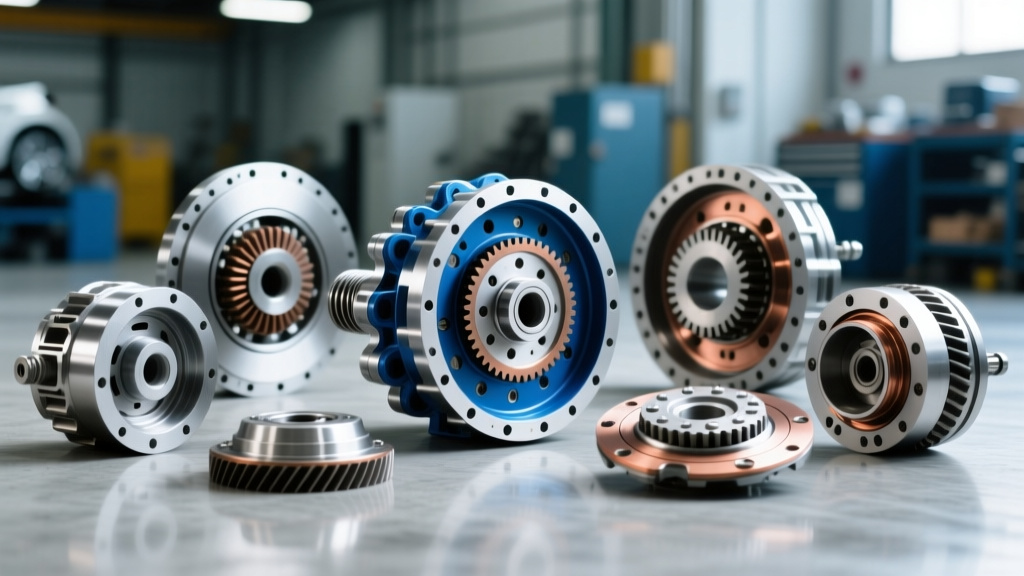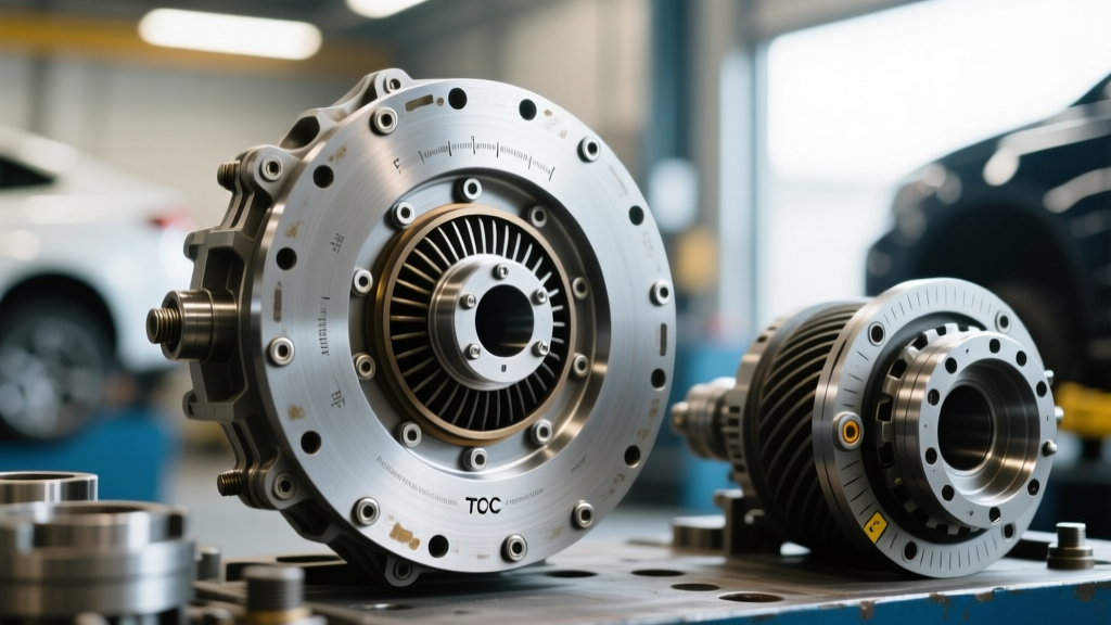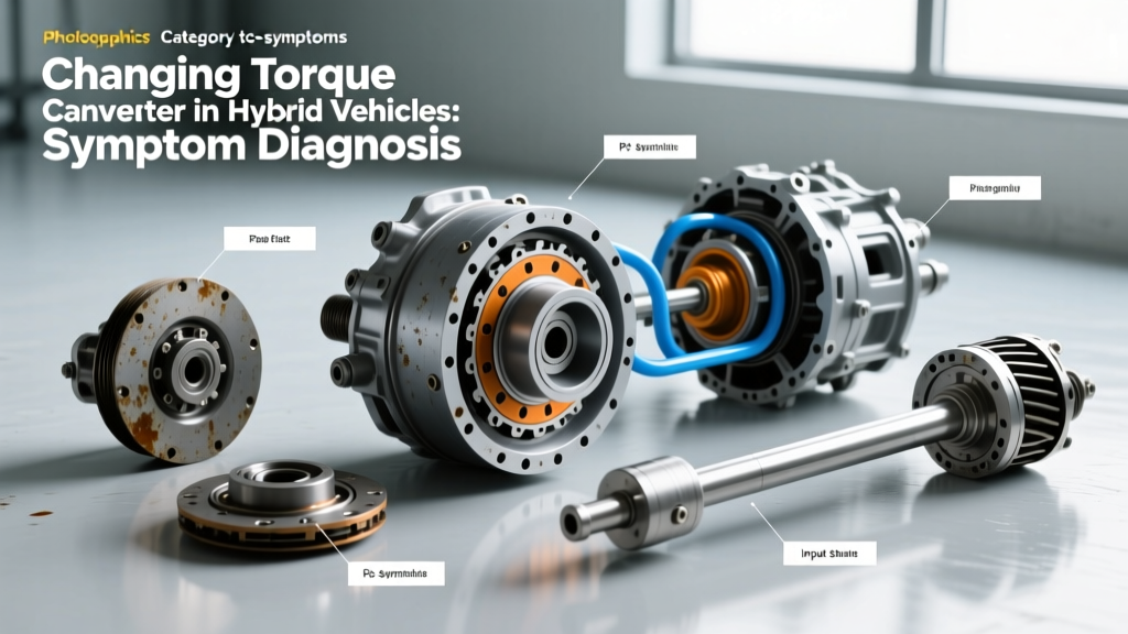
The Hybrid Architecture Divide: Does Your Vehicle Even Have a Torque Converter?
When diagnosing drivetrain vibrations in electrified vehicles, the first step is understanding the underlying architecture. Not all hybrids utilize a traditional fluid coupling. Series-parallel power-split systems, like the Toyota P810 e-CVT found in the Prius and RAV4 Hybrid, rely on planetary gearsets and motor-generators (MG1 and MG2) to manage power delivery. These systems do not have a torque converter, meaning the concept of changing torque converter hardware is entirely irrelevant to them.
However, the automotive landscape in 2026 is dominated by P2 and P3 parallel hybrid architectures. Vehicles like the Ford F-150 PowerBoost (utilizing the 10R80 transmission), BMW PHEVs (utilizing the ZF 8HP75H), and Hyundai/Kia TMED hybrids (using the 6F24 or 8AT) integrate an electric motor directly between the internal combustion engine (ICE) and a traditional automatic transmission. These setups absolutely rely on a torque converter—often heavily modified with integrated torsional dampers and specialized lockup clutches—to manage the massive torque spikes from both the ICE and the electric motor. When these components fail, diagnosing the issue requires a completely different methodology than traditional gas-powered vehicles.
Unique Failure Modes in P2 Hybrid Torque Converters
The torque converter in a P2 hybrid operates under extreme mechanical and thermal stress. Unlike a standard 6L80 or 4L60E transmission where the torque converter clutch (TCC) primarily manages highway cruising efficiency, hybrid TCCs must handle low-speed lockup, regenerative braking torque reversal, and the abrupt torque fill from the electric motor. This leads to three distinct failure modes:
1. Torsional Damper Spring Fatigue
Hybrid torque converters feature multi-stage centrifugal pendulum absorbers (CPA) and heavy-duty torsional springs designed to cancel out the NVH (Noise, Vibration, and Harshness) of ICE cylinder deactivation and EV regen braking. Over time, the constant switching between positive drive (acceleration) and negative torque (regeneration) causes these springs to fatigue or snap, resulting in a deep, metallic clunk during EV-to-ICE handoffs.
2. Carbon-Friction TCC Degradation
To achieve seamless low-speed lockup, hybrid converters use advanced carbon-impregnated friction linings. When subjected to the high thermal loads of frequent stop-and-go electric driving, the lining can glaze or delaminate. This manifests as a high-frequency shudder (typically between 35-55 mph) that mimics a bad wheel bearing or worn CV axle.
3. Electric Motor Cooling Circuit Contamination
In transmissions like the ZF 8HP hybrid variants, the transmission fluid is also used to cool the integrated electric motor. If the motor's internal seals degrade, coolant or stator debris can contaminate the hydraulic circuit, leading to erratic TCC apply pressures and severe shudder.
Symptom Matrix: Traditional vs. Hybrid TC Failure
To accurately isolate the fault, technicians must differentiate between standard torque converter failure and hybrid-specific anomalies. The table below outlines the key diagnostic distinctions:
| Symptom | Traditional ICE Vehicle (e.g., 6L80) | P2 Hybrid Vehicle (e.g., 10R80, ZF 8HP75H) |
|---|---|---|
| Shudder Speed Range | 45-65 mph under light throttle (TCC slip) | 20-55 mph; occurs during EV-to-ICE transition or regen braking |
| Clunk/Noise | Single clunk on engagement; neutral idle noise | Rhythmic metallic rattling during cylinder deactivation (V4/V6 mode) |
| Thermal Behavior | Shudder worsens as fluid temperature exceeds 200°F | Shudder may worsen during high-state-of-charge (SOC) regen braking |
| Scanner PID Anomaly | TCC Slip RPM fluctuates > 50 RPM | Turbine Speed oscillates inversely to Motor-Generator Speed PIDs |
Advanced Diagnostic Troubleshooting Workflow
Before even considering the massive undertaking of changing torque converter assemblies in a hybrid, you must definitively prove the failure using OEM-level bi-directional scan tools. Generic OBD2 scanners are useless for hybrid drivetrain diagnostics.
Step 1: High-Voltage Safety and Scan Tool Setup
Connect your OEM tool (e.g., Ford FDRS/FORScan for the 10R80, or BMW ISTA for the ZF 8HP). Ensure the high-voltage (HV) battery State of Charge (SOC) is above 40% to prevent the ICE from aggressively starting and skewing your data logs during the test drive. Monitor the following critical PIDs:
- TCC_ACTUAL_SLIP: Target is < 15 RPM in full lockup. Oscillations between -40 and +40 RPM indicate friction material failure.
- TURBINE_SPEED vs. IMP_SPEED: Compare turbine speed against the integrated electric motor rotor speed. Discrepancies here point to internal damper failure rather than hydraulic solenoid issues.
- TCC_DUTY_CYCLE: If the Transmission Control Module (TCM) is rapidly pulsing the TCC solenoid duty cycle to compensate for shudder, the adaptive tables are maxed out, confirming mechanical degradation.
Step 2: The Regen-Braking Vibration Test
Drive the vehicle to 50 mph in EV mode (if possible) or with a high HV SOC. Lift off the accelerator to initiate maximum regenerative braking. If a severe driveline shudder occurs exclusively during negative torque application, the torque converter's internal one-way clutch or torsional damper springs have failed. According to technical bulletins published by the SAE International, negative-torque shudder is a primary indicator of CPA (Centrifugal Pendulum Absorber) failure in modern hybrid converters.
Step 3: Fluid Analysis and HV Interlock Check
Pull a fluid sample. In hybrid units, look for a distinct copper or green tint, which indicates electric motor winding or stator coolant contamination. Furthermore, verify that all HV interlock loops are fully seated. A loose HV interlock can cause micro-interruptions in electric motor torque delivery, which perfectly mimics a torque converter shudder to the untrained technician.
The Economics and Logistics of Replacement
The reality of changing torque converter hardware in a P2 hybrid is that it is significantly more expensive and labor-intensive than in a conventional vehicle. The integrated electric motor is often bolted directly to the torque converter housing or the flexplate, requiring specialized alignment tools and high-voltage safety protocols.
Expert Warning: Never attempt to separate the electric motor stator from the torque converter housing on a ZF 8HP hybrid without consulting the OEM high-voltage service manual. Misalignment of the motor resolver by even 0.5mm will result in catastrophic inverter failure upon startup, turning a $3,000 repair into a $12,000 disaster.
Real-World Pricing Breakdown (2026 Estimates)
- Parts (OEM Hybrid TC Assembly): $1,400 to $2,800 (e.g., Ford ML3Z-7902-A for 10R80 PowerBoost).
- Labor (R&R and HV Safety Protocols): 12 to 16 hours at $150-$220/hr ($1,800 - $3,520).
- Fluids, Seals, and Flexplate Bolts: $250 - $400.
- Total Estimated Cost: $3,450 to $6,720.
Because of these costs, many dealerships opt for complete remanufactured transmission assemblies rather than changing torque converter components in-house, as the hybrid bellhousing integration requires clean-room conditions to prevent stator contamination.
Critical Reassembly Specifications
If you are performing the swap, strict adherence to torque specifications and alignment procedures is non-negotiable. Below are the baseline specs for the two most common hybrid architectures on the road today:
Ford 10R80 (F-150 PowerBoost)
- Flexplate-to-Torque Converter Bolts: M10 x 1.25, Torque to 45 Nm (33 lb-ft) + 90 degrees. Must use new stretch bolts.
- Transmission-to-Engine Block Bolts: M12 bolts torqued to 85 Nm (63 lb-ft).
- Fluid Capacity: 13.1 Liters (13.8 qts) of Motorcraft MERCON ULV. Note: Hybrids require strict adherence to the ULV (Ultra Low Viscosity) spec to ensure proper electric motor cooling flow.
ZF 8HP75H (BMW PHEV Applications)
- Flexplate-to-TC Bolts: Torque to 35 Nm (26 lb-ft) using Loctite 243 (blue) on the threads.
- Motor Resolver Alignment: Must be verified using the OEM scan tool's 'Rotor Position Learn' routine after physical installation.
- Fluid Capacity: 9.0 Liters (9.5 qts) of ZF LifeguardFluid 8 (Green). Do not use standard ATF+4 or Dexron VI.
For ongoing safety and compliance data regarding hybrid drivetrain components, technicians should regularly consult the National Highway Traffic Safety Administration (NHTSA) database for active recalls related to HV interlocks and transmission cooling circuits. Additionally, direct OEM technical resources from manufacturers like the ZF Group provide essential updates on hybrid transmission fluid specifications and TCM flashing procedures required after a torque converter replacement.
Final Diagnostic Takeaways
Diagnosing a failing torque converter in a hybrid vehicle requires moving beyond traditional hydraulic logic. By understanding the interplay between the ICE, the electric motor, and the specialized torsional dampers inside the converter, you can accurately pinpoint the root cause of the shudder. Utilize OEM bi-directional scanners to monitor TCC slip and turbine speed oscillations, perform negative-torque regen tests, and always respect the high-voltage safety boundaries. When the time comes for changing torque converter assemblies, invest in OEM-specific alignment tools and ultra-low viscosity fluids to ensure the hybrid system operates seamlessly for another 150,000 miles.