Diagnosing the Heart of the CVT: Why the Torque Converter Matters
When diagnosing shudder, slip, or stall issues in Continuously Variable Transmissions (CVTs) like the JATCO JF011E, JF016E, or Toyota K313, mechanics often overlook the torque converter. Unlike traditional planetary automatics, CVTs rely on aggressive, early lock-up strategies to prevent belt slip and maximize fuel economy. To truly understand CVT drivability complaints, you must look inside of a torque converter designed specifically for belt-and-pulley systems. This step-by-step guide walks you through external diagnostics, fluid forensics, and the physical cut-open inspection of a CVT torque converter, providing the exact specifications and E-E-A-T insights needed for modern transmission repair.
The Unique Role of the Torque Converter in CVT Systems
In a conventional 6-speed or 8-speed automatic, the torque converter multiplies engine torque during initial acceleration and remains unlocked until higher gears. However, a CVT's steel push-belt or chain cannot handle extreme torque multiplication without slipping against the variable pulleys. To protect the variators, CVT control modules command the Torque Converter Clutch (TCC) to apply much earlier—often in late 1st gear or early 2nd gear.
Because the TCC is applied at lower speeds and higher engine loads, the friction material inside of a torque converter in a CVT endures significantly more slip cycles, thermal stress, and micro-shudder events. Furthermore, CVT torque converters utilize specialized multi-stage damper springs to absorb the high-frequency NVH (Noise, Vibration, and Harshness) generated by 4-cylinder engines operating at low RPMs during early lock-up. When these dampers fail or the friction lining degrades, the resulting shudder is often misdiagnosed as a failing valve body or worn pulley set.
Step 1: External Diagnostics and TCC Slip Monitoring
Before dropping the transmission or draining the fluid, you must establish a baseline using a bi-directional scan tool (such as a Snap-on Zeus or Autel MaxiSys). Generic OBD2 scanners cannot read the nuanced TCC slip PIDs required for CVT diagnosis.
Commanding the TCC Solenoid
- Monitor TCC Slip RPM: In a healthy JATCO JF016E (found in newer Nissan Rogues and Altima), commanded slip at highway speeds (60-70 MPH) should hover tightly between 20 and 40 RPM.
- Analyze Fluctuations: If slip fluctuates wildly (e.g., jumping from 10 to 150 RPM rhythmically), the issue is likely degraded friction material inside of the torque converter or a worn TCC control valve bore in the valve body.
- Check Duty Cycle: Command the TCC solenoid manually. If the solenoid duty cycle maxes out but actual slip remains high, the hydraulic circuit is bleeding pressure, or the internal TC piston seals are compromised.
Step 2: Fluid Forensics and Contamination Analysis
CVT fluids (such as Nissan NS-3, Toyota CVTF-FE, or Subaru CVTF-II) contain highly specific friction modifiers designed for both the steel belt and the TCC lining. Draining the pan and analyzing the fluid provides a direct window into the condition of the components inside of a torque converter.
| Debris Type | Visual/Tactile Clue | Internal TC Component Affected |
|---|---|---|
| Black, paper-like flakes | Smears like graphite on a paper towel | TCC Friction Liner (Cellulose/Aramid breakdown) |
| Fine bronze/gold powder | Glitters in sunlight, feels smooth | TC Thrust Washers or Turbine Hub Bushing |
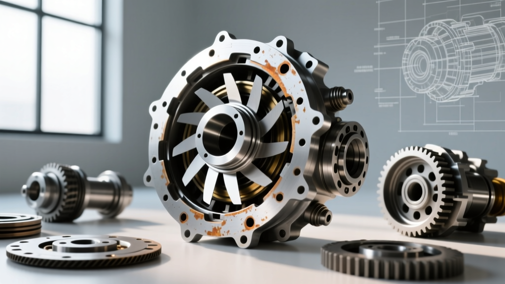
| Chunky metallic shards | Magnetic, sharp edges | Impeller/Turbine Blade Interference or Stator Clutch |
| Dark, burnt-smelling fluid | Acrid odor, fluid is black/brown | TCC Piston Overheating / Glazed Friction Surface |
Expert Insight: If you find heavy black paper-like debris in a JF011E pan, the TCC lining is disintegrating. According to Sonnax technical bulletins, this debris will inevitably migrate to the valve body and clog the TCC apply orifice, requiring a complete flush and valve body service alongside TC replacement.
Step 3: Extraction and Flexplate Separation
Once internal failure is suspected, the transmission must be removed. When separating the CVT from the engine, strict adherence to torque specifications is vital to prevent flexplate warping, which can mimic torque converter shudder.
Key Torque Specs (JATCO JF011E / JF016E Applications)
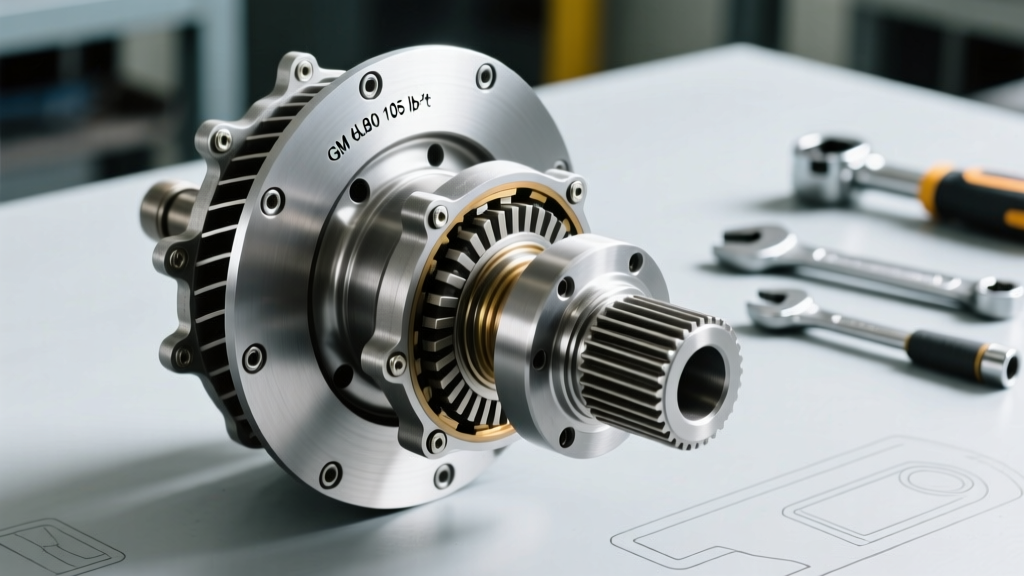
- Flexplate to Torque Converter Bolts (M8): 22 Nm (16 lb-ft). Do not overtighten; these bolts are relatively small and easily snap inside the TC hub.
- Bellhousing to Engine Block (M10/M12): 35 to 45 Nm depending on the specific bellhousing casting.
- Engine to Transmission Mounts: 65 Nm.
Always measure the distance from the flexplate mounting pad to the bellhousing surface before removal. When installing the replacement or rebuilt unit, verify that the TC is fully seated into the transmission oil pump. A CVT torque converter typically requires three distinct 'clicks' or drops as it engages the stator support shaft, the turbine splines, and the oil pump drive gear. Failure to fully seat the TC will result in immediate oil pump destruction upon startup.
Step 4: Looking Inside of the Torque Converter (Cut-Open Procedure)
For advanced rebuilders and diagnostic specialists, cutting open a failed CVT torque converter reveals the exact failure mechanism. This requires a specialized TC cutting lathe and carbide cutting tools. According to guidelines from the Automatic Transmission Rebuilders Association (ATRA), safety and precision are paramount when splitting the outer weld.
Inspecting the Internal Architecture
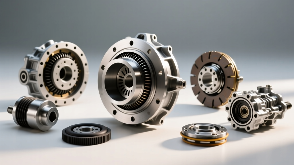
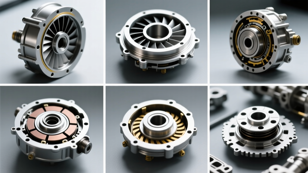
Once the outer cover is removed, you will expose the unique architecture inside of a torque converter built for CVT applications:
- The TCC Piston and Friction Liner: CVT TCC pistons often feature a multi-plate clutch pack or a highly specialized woven carbon/aramid single-plate liner designed to handle continuous micro-slip. Look for heat checking (cracking) on the apply surface of the front cover, which occurs when the TCC is commanded to slip at low speeds to manage NVH.
- Multi-Stage Damper Springs: Unlike the simple coil springs in older automatics, CVT converters use complex, multi-stage torsional dampers. These springs are tuned to specific frequencies. If you find shattered springs or loose retaining tabs, the converter has been subjected to severe torsional shock, often caused by engine misfires or aggressive tuning.
- The Stator and One-Way Clutch: The stator blades in a CVT torque converter are pitched differently than those in planetary automatics. Because CVTs keep the engine in a narrow, optimal RPM band, the stator is optimized for low-RPM efficiency rather than high-stall torque multiplication. Inspect the one-way clutch sprags; if they are rounded off, the stator will freewheel in both directions, resulting in a severe lack of low-speed power and delayed vehicle movement.
Step 5: Rebuilding vs. Replacing the CVT Torque Converter
While cutting open a TC is excellent for root-cause analysis, repairing it requires specialized welding equipment, dynamic balancing machines, and pressurized leak-testing rigs. For most shops, installing a remanufactured unit is the most reliable path.
Cost Breakdown and Part Numbers
- OEM Replacement: A brand-new OEM torque converter from JATCO (e.g., Part Number 31100-1XF0A for Nissan Altima 2.5L applications) typically ranges from $750 to $1,100.
- Remanufactured Units: High-quality remanufactured converters with upgraded TCC linings and reinforced damper springs cost between $350 and $550.
- Rebuild Kits: If you possess in-house TC rebuilding capabilities, a Sonnax TCC rebuild kit (including new friction rings, seals, and O-rings) costs roughly $85 to $150 per unit.
- Labor Time: Standard book time for CVT transmission removal and torque converter replacement is 6.5 to 8.5 hours, translating to $900 to $1,400 in labor at standard independent shop rates.
Final Thoughts on CVT Drivability
Diagnosing shudder in a Continuously Variable Transmission requires looking beyond the valve body and the belt-and-pulley assembly. Because the TCC is applied so early and frequently, the friction components inside of a torque converter are subjected to immense thermal and mechanical stress. By combining bi-directional scan tool data, meticulous fluid forensics, and an understanding of CVT-specific internal architecture, technicians can accurately pinpoint torque converter failures, prevent comebacks, and restore the seamless drivability that CVT systems were designed to deliver.