The TCM Logic: Why 'Incorrect Gear Ratio' Codes Set
When a Transmission Control Module (TCM) throws a P0730 (Incorrect Gear Ratio) or a gear-specific code like P0731 through P0736, it is not guessing. The TCM is performing a continuous, real-time mathematical comparison between the Input Shaft Speed (ISS) and the Output Shaft Speed (OSS). To understand how to fix incorrect gear ratio faults, a technician must first understand how to calculate gear ratio data exactly as the TCM does. If the calculated ratio deviates from the commanded ratio map by more than 5% to 10% for a specific duration, the TCM assumes mechanical slip, a hydraulic failure, or a sensor fault, and sets a Diagnostic Trouble Code (DTC).
In 2026, with the proliferation of 8-speed and 10-speed automatics, the margin for error has shrunk. Overlapping clutch apply strategies in units like the ZF 8HP and GM 10L90 mean that a minor pressure leak can cause a micro-slip that the TCM immediately flags. Below is the definitive technical guide on calculating these ratios and executing the correct mechanical or electrical repairs.
How to Calculate Gear Ratio: Digital vs. Physical Methods
Before tearing down a transmission, you must verify whether the 'incorrect ratio' is a mathematical reality or an electrical illusion. There are two primary ways to calculate the gear ratio: digitally via live OBD-II data, and physically via mechanical measurement.
1. Digital Calculation via OBD-II PIDs
The most efficient way to calculate the active gear ratio is by monitoring live data Parameter IDs (PIDs) using a bi-directional scan tool. The universal formula the TCM uses is:
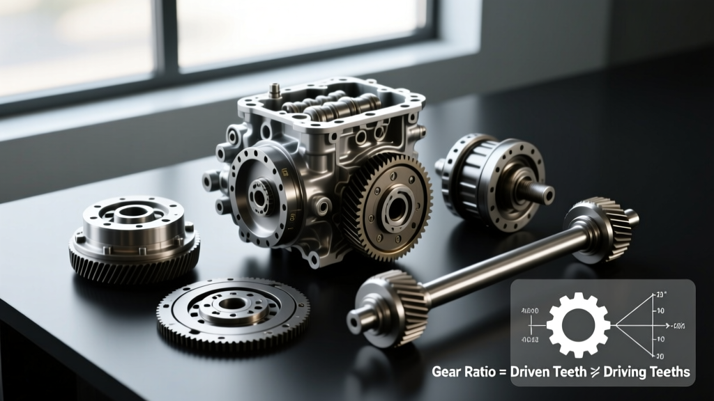
Gear Ratio = Input Shaft Speed (ISS) / Output Shaft Speed (OSS)
- Step 1: Connect your scan tool and graph the ISS and OSS RPM PIDs simultaneously.
- Step 2: Drive the vehicle and command the specific gear that is setting the code (e.g., 3rd gear for a P0733).
- Step 3: Record the RPMs at a steady-state throttle. If the ISS reads 2,200 RPM and the OSS reads 1,800 RPM, your calculated ratio is 1.22:1 (2200 / 1800).
- Step 4: Compare this to the factory specification. If 3rd gear is supposed to be a 1.00:1 direct drive, a 1.22:1 actual ratio confirms severe clutch pack slippage or a cross-leak in the valve body.
2. Physical Calculation: The Tire Spin Method (Axle Ratio)
If you suspect an aftermarket final drive or axle ratio was installed without updating the TCM's configuration tables (a common cause of P0730 codes on modified trucks), you must calculate the physical final drive ratio. Jack up the drive wheels, mark the driveshaft and the tire, and rotate the tire exactly one full revolution while counting the driveshaft rotations. If the driveshaft rotates 3.73 times, your physical axle ratio is 3.73:1. You must then cross-reference this with the TCM's programmed final drive ratio in the calibration file.
3. Physical Calculation: Planetary Gearset Mathematics
During a teardown, you can calculate the ratio of a simple planetary gearset by counting teeth. The formula for a standard Simpson or Ravigneaux gearset holding the carrier and driving the sun gear is:
Ratio = 1 + (Ring Gear Teeth / Sun Gear Teeth)
For example, if the ring gear has 72 teeth and the sun gear has 30 teeth, the ratio is 1 + (72/30) = 3.40:1. Verifying these physical components ensures the correct hard parts were installed during a previous rebuild.
Reference Table: Expected Gear Ratios for Common Transmissions
Use this reference table to compare your digitally calculated ratios against factory specifications. According to Automatic Transmission Rebuilders Association (ATRA) guidelines, deviations greater than 0.05 from these baselines usually indicate hydraulic or friction material failure.
| Transmission Model | Gear 1 | Gear 2 | Gear 3 | Gear 4 | Common DTCs |
|---|---|---|---|---|---|
| GM 4L60E | 3.06:1 | 1.63:1 | 1.00:1 | 0.70:1 | P0733 (3rd), P0734 (4th) |
| GM 6L80 | 4.03:1 | 2.36:1 | 1.53:1 | 1.15:1 | P0731, P0732 |
| ZF 8HP45 / 8HP70 | 4.71:1 | 2.99:1 | 2.15:1 | 1.77:1 | P0730, P0735 |
| Ford 10R80 | 4.70:1 | 2.99:1 | 2.15:1 | 1.77:1 | P0736 (Reverse) |
How to Fix Incorrect Gear Ratio Codes: Real-World Scenarios
Once you have calculated the gear ratio and confirmed a deviation, the repair path depends on the specific transmission architecture and the gear in question. Below are three highly specific diagnostic and repair scenarios.
Scenario 1: GM 4L60E Setting P0733 (Incorrect 3rd Gear Ratio)
The Diagnosis: In the 4L60E, 3rd gear requires the application of the 3-4 clutch pack and the forward clutch band. If your scan tool shows an ISS/OSS ratio of 1.15:1 in 3rd gear, the 3-4 clutch pack is slipping. This is the most notorious failure point of the 4L60E due to the small surface area of the OEM friction plates.
The Fix: You must remove the transmission and rebuild the 3-4 clutch drum. Do not reuse the OEM plastic retainers. Upgrade to a high-capacity kit, such as the Sonnax Smart-Tech 3-4 clutch kit. When reassembling, the valve body to case bolts must be torqued to exactly 11 Nm (8 lb-ft) in a star pattern to prevent valve body warping, which causes cross-leaks that mimic clutch failure. The transmission pan bolts should be torqued to 16 Nm (12 lb-ft). Refill with Dexron VI fluid.
Scenario 2: ZF 8HP70 Setting P0731 or P0732 (Mechatronic Seal Leaks)
The Diagnosis: The ZF 8-speed relies on a highly pressurized mechatronic unit bolted directly to the valve body inside the pan. If you calculate a ratio slip in 1st or 2nd gear, but the clutch packs measure perfectly within spec during an air-check, the fault is almost always a pressure leak at the mechatronic adapter sleeve. The rubber seals degrade, bleeding apply pressure away from the A and B clutches.
The Fix: Drop the integrated plastic transmission pan (which houses the filter). Remove the mechatronic unit. Replace the mechatronic adapter sealing sleeve (ZF Part # 241.010 or equivalent aftermarket). The valve body to transmission case torque specification is critical: 10 Nm (7.4 lb-ft). Over-torquing will crack the aluminum valve body casting. Refill using only ZF LifeguardFluid 8, as friction modifiers in generic ATFs will cause immediate shudder and ratio slip codes. For deeper diagnostic flows, refer to Sonnax Technical Resources.
Scenario 3: Electrical Illusions - ISS and OSS Sensor Faults
The Diagnosis: If your calculated ratio is erratic, jumping from 1.00:1 to 4.00:1 and back while cruising at a steady speed, you do not have a mechanical slip. You have a signal dropout. The TCM is calculating the ratio based on corrupted sensor data. Hall-effect speed sensors are susceptible to heat soak and wiring chafe.
The Fix: Back-probe the ISS and OSS sensors with an oscilloscope. You should see a clean, square-wave DC voltage signal that increases in frequency with RPM. If the signal drops out, inspect the harness. If the wiring is intact, replace the sensor. For GM applications, the AC Delco ISS/TSS sensor (Part # 213-4383) is the OEM standard. Clear the TCM adaptive learning tables after replacement to allow the system to relearn the new sensor's signal latency.
Summary Framework for Drivability Technicians
Knowing how to calculate gear ratio is the dividing line between a parts-replacer and a true drivability technician. Never replace a transmission based solely on a P0730 code. Always graph the ISS and OSS PIDs, calculate the exact mathematical deviation, and cross-reference the specific clutch apply charts for the transmission in question. Whether you are torquing a ZF 8HP valve body to 10 Nm or upgrading a 4L60E clutch drum, precision in both calculation and mechanical assembly is the only way to permanently fix incorrect gear ratio codes.
For standardized code definitions and baseline diagnostic trees, technicians frequently consult the OBD-Codes P0730 Definition database to verify manufacturer-specific enable criteria before beginning teardown procedures.