The Critical Role of Hydraulic Clutch Systems
Modern manual transmissions rely heavily on hydraulic actuation to transfer driver input from the clutch pedal to the release bearing. Unlike legacy cable-operated systems, hydraulic setups utilize Pascal's Law to multiply force, providing a lighter pedal feel and more precise engagement modulation. However, this closed-loop fluid system is highly susceptible to contamination, aeration, and component degradation. When symptoms like gear grinding, a spongy pedal, or incomplete disengagement arise, accurate hydraulic clutch system diagnosis is mandatory. This preventive maintenance guide details the exact procedures for bleeding hydraulic clutch circuits, identifying failure points, and extending the lifespan of your drivetrain components.
Anatomy of a Modern Hydraulic Clutch Circuit
Before attempting any repair, it is vital to understand the architecture of the system. A standard hydraulic clutch circuit consists of four primary components:
- Master Cylinder: Typically mounted on the firewall or directly to the pedal box. OEM manufacturers like FTE, ATE, and Sachs produce cylinders with internal bypass ports that compensate for fluid expansion and clutch wear.
- Hydraulic Lines: A combination of hard metal tubing (usually steel or cupro-nickel) routed through the chassis, and flexible rubber or braided stainless-steel hoses that accommodate engine movement.
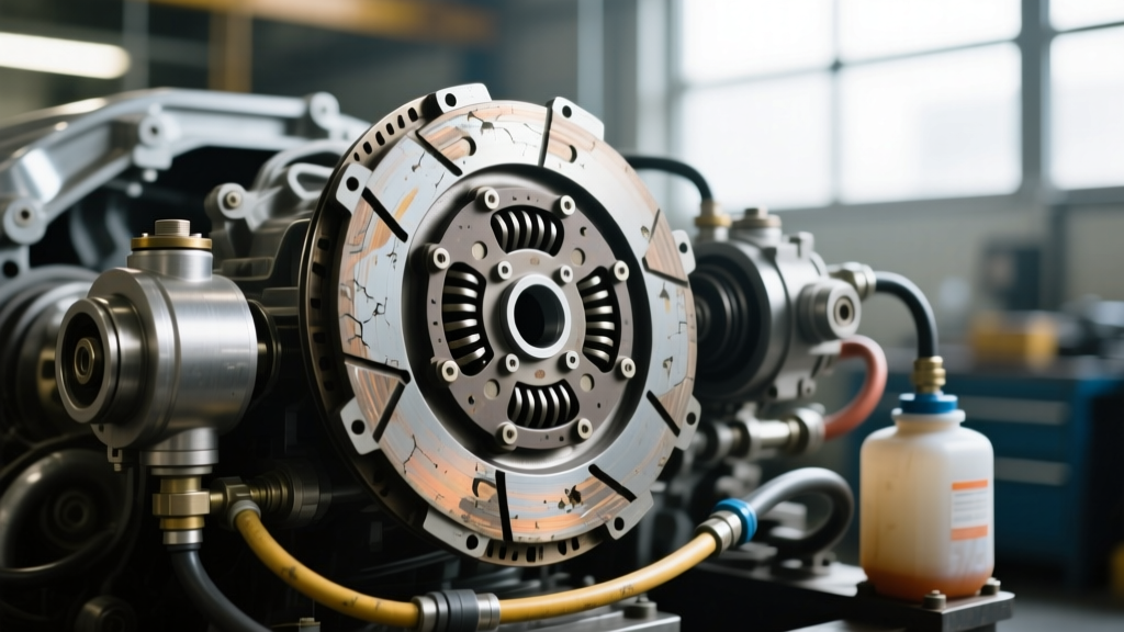
- Slave Cylinder: This actuator receives the hydraulic pressure. It can be an External Slave Cylinder (mounted on the outside of the bellhousing, common on Tremec T56 Magnum and Ford MT82 applications) or a Concentric Slave Cylinder (CSC) (mounted inside the bellhousing, directly over the transmission input shaft, standard on most modern ZF and Porsche transaxles).
- Hydraulic Fluid: Most systems share the brake master cylinder reservoir and utilize glycol-ether based DOT 3, DOT 4, or DOT 5.1 fluid.
Diagnosing Hydraulic Clutch Symptoms
Accurate diagnosis prevents unnecessary parts replacement. A spongy pedal does not always mean the master cylinder is dead; it often indicates aerated fluid or a failing flexible line. Use the diagnostic matrix below to isolate the root cause of your clutch system symptoms.
Symptom Probable Root Cause Diagnostic Verification Corrective Action Spongy or Soft Pedal Air in the hydraulic line or hygroscopic fluid boiling Pump pedal 5 times, hold pressure. If pedal slowly sinks to the floor, internal bypass leak or air is present. Perform reverse pressure bleeding; flush with fresh high-temp DOT 4 fluid. Gear Grinding on Shifts Incomplete clutch disengagement (drag) Measure pedal free-play. Check for collapsed flexible rubber hose acting as a one-way check valve. Replace flexible hose; adjust master cylinder pushrod depth if adjustable. Pedal Sticking to Floor Failed clutch pressure plate fingers or seized slave cylinder Inspect external slave travel. If travel is normal but clutch won't release, issue is mechanical inside bellhousing. Transmission removal required. Replace LUK or Sachs clutch kit and CSC. Fluid Loss (No visible drip) Leaking Concentric Slave Cylinder (CSC) Check brake fluid reservoir level. Inspect bellhousing weep hole for fluid seepage. Drop transmission. Replace CSC, clutch disc, and pressure plate as a matched set. Edge Case: The Failing Concentric Slave Cylinder (CSC)
Concentric Slave Cylinders are notorious for catastrophic failure around the 60,000 to 80,000-mile mark. Because the CSC acts as both the hydraulic actuator and the throw-out bearing, a blown CSC seal will dump DOT fluid directly onto the clutch friction material, ruining the disc. When diagnosing a suspected CSC leak, always look for a wet, oily residue around the transmission bellhousing weep plug. If confirmed, never replace just the CSC. Always install a complete matched kit (such as a LUK RepSet) to ensure the hydraulic preload and clutch stack-up height remain within factory tolerances.
Master Guide to Bleeding Hydraulic Clutch Systems
Air is the enemy of hydraulic systems. Because air is a gas, it compresses under pressure, resulting in lost pedal travel and incomplete clutch disengagement. Furthermore, the clutch hydraulic line often routes upward from the master cylinder, over the transmission, and down to the slave cylinder, creating natural high-point traps for air bubbles. Here are the three primary methods for bleeding hydraulic clutch circuits.
Method 1: Gravity Bleeding (The Passive Approach)
Gravity bleeding is the safest method for older, brittle brass bleeder valves, though it requires patience.
- Clean the master cylinder reservoir cap and fill with fresh, sealed DOT 4 fluid.
- Attach a clear vinyl tube to the slave cylinder bleeder valve, routing the other end into a catch bottle partially filled with fluid (to submerge the tube end).
- Open the bleeder valve exactly one-half turn.
- Allow gravity to pull the fluid through the system over 2 to 4 hours. Keep a strict eye on the master reservoir to ensure it never runs dry, which will introduce massive air pockets.
- Close the valve when the fluid runs completely clear and bubble-free.
Method 2: Manual Two-Person Pumping
This traditional method requires an assistant. The driver pumps the clutch pedal 3 to 5 times and holds it to the floor. The assistant opens the bleeder valve, allowing fluid and air to escape, then closes it before the driver releases the pedal. Warning: Never let the driver release the pedal while the bleeder valve is open, as this will suck air backward through the threads of the valve.
Method 3: Reverse Pressure Bleeding (The Professional Standard)
Reverse bleeding is the most effective technique for stubborn clutch systems. By forcing fluid from the lowest point (the slave cylinder) upward to the master cylinder, you work with the natural buoyancy of air bubbles.
Pro-Tip from the Bench: When reverse bleeding, use a motive bleeder or a large syringe to push fluid UP into the slave cylinder bleeder. Watch the master cylinder reservoir closely. As the displaced fluid rises, use a turkey baster to extract the old, aerated fluid from the top of the reservoir so it doesn't overflow onto your paint.
Tools like the Motive Products 0100 Power Bleeder can be adapted with specific master cylinder cap adapters to pressurize the system from the top down, but for the clutch circuit specifically, pushing from the bottom via a syringe or pneumatic reverse bleeder yields the fastest, most bubble-free results.
Preventive Maintenance Schedule and Fluid Selection
Glycol-based hydraulic fluids are highly hygroscopic, meaning they absorb moisture from the atmosphere through microscopic pores in rubber hoses and reservoir vents. According to the FMVSS 116 DOT Fluid Standards, DOT 4 fluid has a dry boiling point of 230°C (446°F), but its wet boiling point (with 3.7% water content) drops drastically to 155°C (311°F). Boiling fluid creates vapor lock, leading to a sudden, total loss of clutch pedal pressure.
For high-performance or heavy-duty towing applications, upgrading to a high-dry-boiling-point fluid like Motul RBF 600 High-Performance Fluid provides a dry boiling point of 312°C (594°F), offering immense safety margins against vapor lock during aggressive track use or steep mountain descents.
Recommended Service Intervals
- Standard Commuter Vehicles: Flush and bleed hydraulic clutch fluid every 3 years or 45,000 miles.
- Performance / Track Vehicles: Flush annually or every 15,000 miles using high-temp DOT 4 or DOT 5.1 fluid.
- Heavy Duty / Towing: Inspect flexible lines for bulging every 30,000 miles; replace rubber hoses with braided stainless-steel lines (e.g., Goodridge or Russell) to prevent volumetric expansion under heavy load.
Torque Specifications and Reassembly Data
When replacing master or slave cylinders during your diagnosis, adhering to precise torque specifications is critical. Over-torquing can crack cast aluminum housings or snap brass bleeder screws, while under-torquing leads to leaks and misalignment. Always consult your specific service manual, but use these industry-standard baselines as a reference:
- Master Cylinder Mounting Nuts (M8): 15 - 20 Nm (11 - 15 lb-ft)
- External Slave Cylinder Mounting Bolts (M8): 25 - 35 Nm (18 - 25 lb-ft)
- Concentric Slave Cylinder (CSC) Mounting Bolts (M6): 8 - 10 Nm (6 - 7 lb-ft) Use medium-strength threadlocker.
- Brass Bleeder Valve: 8 - 10 Nm (6 - 7 lb-ft) Never use an impact wrench; brass seizes and snaps easily inside the steel cylinder body.
- Hydraulic Line Banjo Bolts: 20 - 25 Nm (15 - 18 lb-ft) Always use two new copper or aluminum crush washers.
Final Thoughts on Drivetrain Longevity
Proper hydraulic clutch system diagnosis requires looking beyond the pedal and understanding the fluid dynamics at play. By implementing a strict preventive maintenance schedule, utilizing high-quality hygroscopic fluids, and mastering the reverse-bleeding technique, you can eliminate spongy pedals and ensure crisp, reliable gear changes for the life of your manual transmission. For further technical bulletins and installation guides regarding specific manual gearbox applications, refer to Tremec Drivetrain Support or your vehicle manufacturer's OEM service portal.