The Critical Role of Center Differential Fluid in AWD Systems
All-wheel-drive (AWD) vehicles rely on the center differential to manage torque distribution between the front and rear axles. Unlike standard open differentials, AWD center diffs utilize complex internal architectures—such as planetary gearsets, viscous couplers, or helical worm gears (Torsen)—to prevent slip and maintain traction. In the 2026 diagnostic landscape, relying on guesswork when an AWD system binds, whines, or shudders is a recipe for catastrophic drivetrain failure. True expertise requires cross-referencing physical symptoms with a factory car differential diagram and understanding the precise rheology of the gear oil or specialized transfer case fluid lubricating the system.
'The center differential is the heart of any AWD system. When fluid shear breaks down the extreme pressure (EP) additives, the mechanical tolerances collapse. A diagram doesn't just show you where the gears are; it shows you where the fluid galleries feed the clutch packs and bearings.'
Decoding the Car Differential Diagram for Fluid Diagnosis
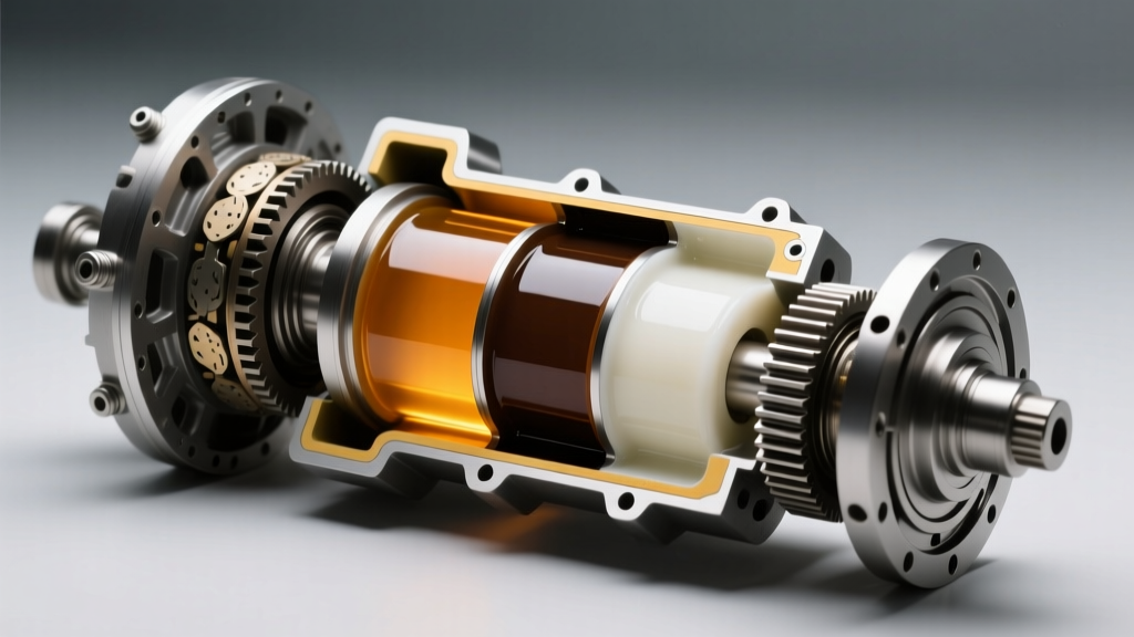
When troubleshooting drivetrain NVH (Noise, Vibration, and Harshness) or binding, a mechanic must first consult a comprehensive car differential diagram. This schematic reveals the internal oil pump mechanisms, fluid gallery routing, and clutch pack clearance zones. For instance, in electronically controlled center differentials, the diagram will highlight the solenoid valves that regulate hydraulic pressure to the multi-plate clutches. If the fluid is degraded, contaminated with clutch material, or lacks the correct friction modifiers, the solenoid screens clog, resulting in delayed torque transfer and violent shuddering during acceleration.
Symptom-to-Fluid Failure Matrix
Use the following diagnostic matrix to correlate driver complaints with specific fluid degradation modes and internal mechanical faults.
| Symptom | Probable Internal Fault | Fluid / Diagram Indicator | Diagnostic Action |
|---|---|---|---|
| Binding/chirping on tight, low-speed turns | Viscous coupler silicone expansion or LSD clutch glazing | Fluid galleries show cross-axle lockup; EP additives depleted | Drain and inspect for metallic paste; verify friction modifier spec |
| High-pitched whine under deceleration | Worm gear micro-pitting or hypoid gear bearing wear | Diagram points to pinion bearing feed gallery; fluid viscosity loss | Magnetic plug inspection; check for silicon contamination |
| Shudder during hard acceleration from a stop | Multi-plate clutch pack slip/stick | Solenoid feed channels restricted by degraded fluid particulates | Flush system; replace with OEM-spec fluid containing correct modifiers |
| Clunking when shifting from Reverse to Drive | Excessive planetary gear backlash or worn spider gears | Low fluid level causing cavitation and poor hydraulic damping | Verify fill level to the bottom of the fill hole; check for leaks |
Platform-Specific Diagnostics: Subaru, Audi, and Toyota
Subaru Symmetrical AWD: Viscous Coupling and DCCD
Subaru's manual and DCCD (Driver Controlled Center Differential) systems are legendary, but they are highly sensitive to fluid chemistry. The mechanical limited-slip portion of the DCCD requires a specific friction-modified 75W-90 GL-5 gear oil, such as Subaru Extra MT (Part # SOA635040). If a shop mistakenly fills this with a standard, non-modifier GL-5 fluid, the clutch packs will chatter violently. Conversely, older viscous center diffs rely on a sealed silicone fluid inside the coupler, surrounded by standard hypoid gear oil. If the internal seals fail, the silicone leaks into the main gear oil cavity, causing the center diff to permanently lock. A car differential diagram of the Subaru viscous unit clearly shows the isolation barrier between the outer gear oil bath and the inner silicone chamber.
- Subaru DCCD Drain/Fill Plug Torque: 44 Nm (32.5 ft-lbs)
- Fluid Capacity: Approximately 0.8 to 1.0 Liters (varies by exact transmission casing)
- Failure Tell: Black, glittering sludge on the drain plug indicates mechanical LSD clutch pack disintegration.
Audi Quattro: Torsen Type C and Crown Gear Systems
Audi's Quattro systems evolved from the classic Torsen Type A to the Torsen Type C (Crown Gear). These units utilize helical worm gears that rely on extreme axial thrust to generate torque bias. According to Audi engineering documentation available via Ross-Tech's technical archives, these systems require highly specialized fluids like G 055 145 A2 or G 060 175 A2. Standard GL-5 gear oils contain sulfur-phosphorus EP additives that can corrode the yellow metals (brass/bronze synchronizers) found in the integrated manual transmission, or fail to provide the specific film strength required for the Torsen worm gears. If an Audi Quattro whines under load, consult the diagram to locate the crown gear thrust bearings; fluid starvation here leads to immediate housing scoring.
- Audi Transfer Case / Center Diff Fill Plug Torque: 25 Nm (18.4 ft-lbs)
- Fluid Spec Warning: Never substitute with off-the-shelf 75W-90 GL-5 without verifying yellow-metal safety and OEM friction requirements.
Toyota / Lexus: VF4B and Torsen Center Diffs
Toyota's truck and SUV AWD systems (like the 4Runner and Land Cruiser) often use the VF4B or similar Torsen-based transfer cases. These are robust but require 75W-85 GL-5 gear oil. A common misdiagnosis occurs when drivers report a 'binding' sensation in 4WD Auto. By reviewing the car differential diagram for the VF4B, technicians can see the actuator motor and shift forks. Often, the issue isn't the fluid inside the Torsen unit itself, but the degraded ATF in the adjacent actuator housing or transfer case chain stretch. However, if the whine is isolated strictly to the center diff, the hypoid gear oil has likely lost its viscosity index due to severe thermal cycling.
Step-by-Step Fluid Verification and Service Protocol
When the diagram and symptoms point to fluid degradation, a precise service protocol must be followed to avoid introducing air pockets or contaminants.
- Thermal Preparation: Drive the vehicle for 15-20 minutes to bring the center diff fluid to operating temperature (approx. 140°F - 160°F). This ensures suspended metallic particulates and degraded silicone are fully drained.
- Plug Sequence: ALWAYS remove the fill plug before the drain plug. If the fill plug is seized or stripped, you do not want to be left with an empty differential and no way to refill it.
- Magnetic Inspection: Wipe the magnetic drain plug on a white paper towel. Fine gray paste is normal clutch wear. Sharp metallic flakes or brass-colored shavings indicate bearing or synchronizer failure requiring a teardown.
- Refill and Leveling: Pump the OEM-specified fluid until it weeps from the fill hole. Wait 3 minutes for the fluid to settle into the complex gallery networks shown in your car differential diagram, then top off to the exact bottom lip of the fill hole.
- Post-Service Calibration: For electronically managed center diffs (e.g., Subaru DCCD, modern torque-vectoring units), use a bi-directional scan tool to cycle the solenoids and bleed air from the hydraulic clutch packs.
Expert Insights on Fluid Chemistry and Additive Depletion
As detailed in extensive tribology discussions on Bob Is The Oil Guy, the friction modifiers in center differential fluids are sacrificial. Over 30,000 to 50,000 miles, the long-chain polymers that allow clutch plates to slip-and-grip smoothly shear down into shorter chains. This results in a 'stick-slip' phenomenon, felt by the driver as a shudder. Furthermore, the sulfur-phosphorus EP additives, which protect the hypoid ring and pinion gears under extreme sliding pressures, deplete and form acidic byproducts. If left unchanged, these acids etch the bearing races, leading to the characteristic deceleration whine that signals imminent mechanical death.
Ultimately, mastering AWD drivetrain diagnosis requires moving beyond basic code reading. By combining the structural roadmap provided by a detailed car differential diagram with a deep understanding of fluid chemistry, torque specifications, and mechanical failure modes, technicians can accurately isolate center differential faults before they escalate into multi-thousand-dollar drivetrain replacements.
For further OEM service procedures and torque specifications, always refer to the manufacturer's official portal, such as Subaru TechInfo or your respective brand's technical information system.