The Leap from STEM to the Shop Bay
For many engineering students and hobbyists, VEX IQ drivetrains serve as the foundational introduction to power transfer, gear ratios, and torque multiplication. Building a chain-driven or gear-driven chassis in a STEM lab teaches the fundamental physics of rotational force. However, transitioning from the lightweight, low-torque environment of robotics to the brutal, high-load reality of automotive drivetrain component identification requires a massive paradigm shift. In the real world, a miscalculated gear mesh or an under-torqued fastener doesn't just drop a plastic axle; it shatters a differential housing or destroys a ZF 8HP transmission output flange.
As of 2026, the line between theoretical robotics and applied automotive mechanics is bridged by advanced diagnostic tools and precise component identification. Whether you are diagnosing a clunk in a GM 6L80-equipped truck or tracking down a high-speed vibration in a BMW with a ZF 8HP45, understanding how to identify, measure, and troubleshoot real-world drivetrain components is critical. This guide translates foundational STEM concepts into professional-grade automotive symptom diagnosis.
Translating VEX IQ Concepts to Heavy-Duty Automotive Systems
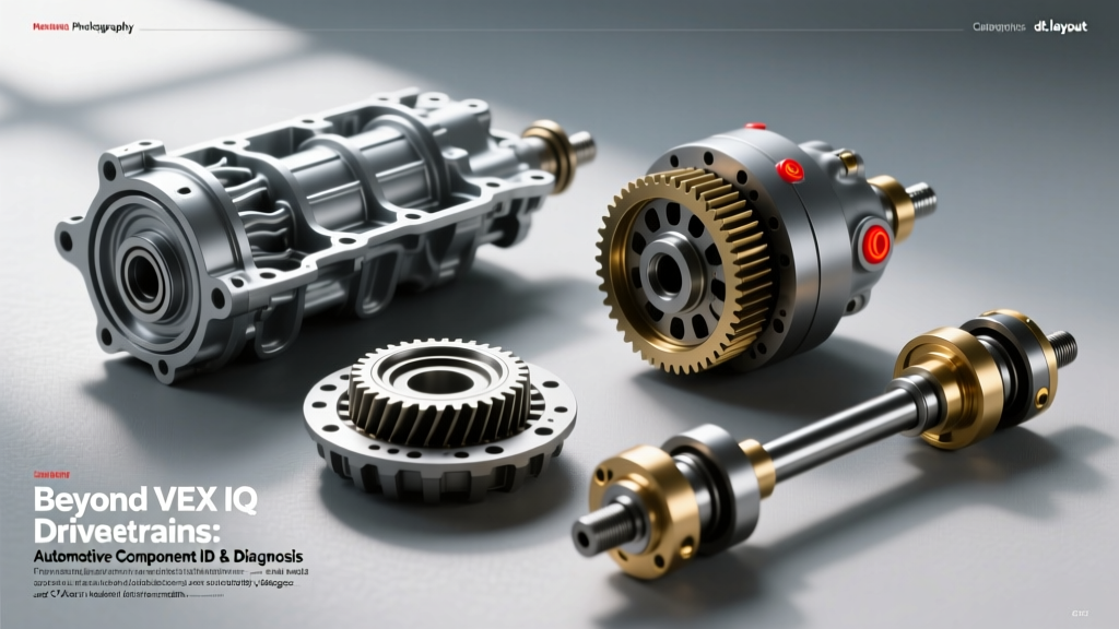
Before tearing into a driveshaft or dropping a differential, we must map the micro-components of VEX IQ drivetrains to their massive, forged-steel automotive counterparts. The physics remain identical, but the tolerances, materials, and failure modes are exponentially more complex.
| VEX IQ Drivetrain Concept | Automotive Equivalent | Real-World Application & Failure Mode |
|---|---|---|
| Chain & Sprocket Drive | Transfer Case Chain / Timing Chain | BorgWarner 42-34 chains in NV246 transfer cases. Failure: Chain stretch causing 'binding' in AWD modes. |
| Spur & Bevel Gears | Planetary Gearsets / Ring & Pinion | Ravigneaux gearsets in Ford 10R80. Failure: Sun gear shell cracking under high-torque tuning. |
| Shaft Collars & Bearings | U-Joints, CV Joints, Carrier Bearings | Spicer 1310 U-joints. Failure: Needle bearing cap starvation leading to trunnion galling and driveshaft separation. |
| Direct Drive Couplings | Flexplates, Torque Converters, Couplings | ZF 8HP torsional dampers. Failure: Spring fatigue causing idle rattle and bell-housing resonance. |
Symptom Diagnosis: Identifying and Specifying Real-World Components
When a customer complains of a 'vibration at 65 mph' or a 'clunk when shifting into reverse,' a technician must isolate the exact component. Unlike VEX IQ drivetrains where components are easily swapped, automotive drivetrains require precise identification, strict torque specifications, and exact fluid compatibilities.
U-Joints, Yokes, and Driveshaft Phasing
The universal joint (U-joint) is the automotive equivalent of a multi-axis pivot. The most common light-duty U-joint is the Spicer 1310 series (Part # 5-153X). When diagnosing a driveline clunk, the first step is checking U-joint play. However, identifying the failure requires looking at the yoke and strap hardware.
- Torque Spec: The strap bolts securing a Spicer 1310 U-joint to a GM 6L80 transmission output yoke must be torqued to exactly 16 lb-ft. Over-torquing distorts the bearing caps, binding the needles and causing premature failure.
- Runout Measurement: Using a magnetic dial indicator, driveshaft runout must not exceed 0.010 inches near the weld yoke. Excessive runout indicates a bent tube, often misdiagnosed as a bad U-joint.
- Phasing Errors: If a two-piece driveshaft is reassembled out of phase (the yokes not aligned in the same plane), it will cause a severe 2nd-order vibration. This is a common error after replacing a center carrier bearing.
CV Axles and ZF 8HP Output Flange Failures
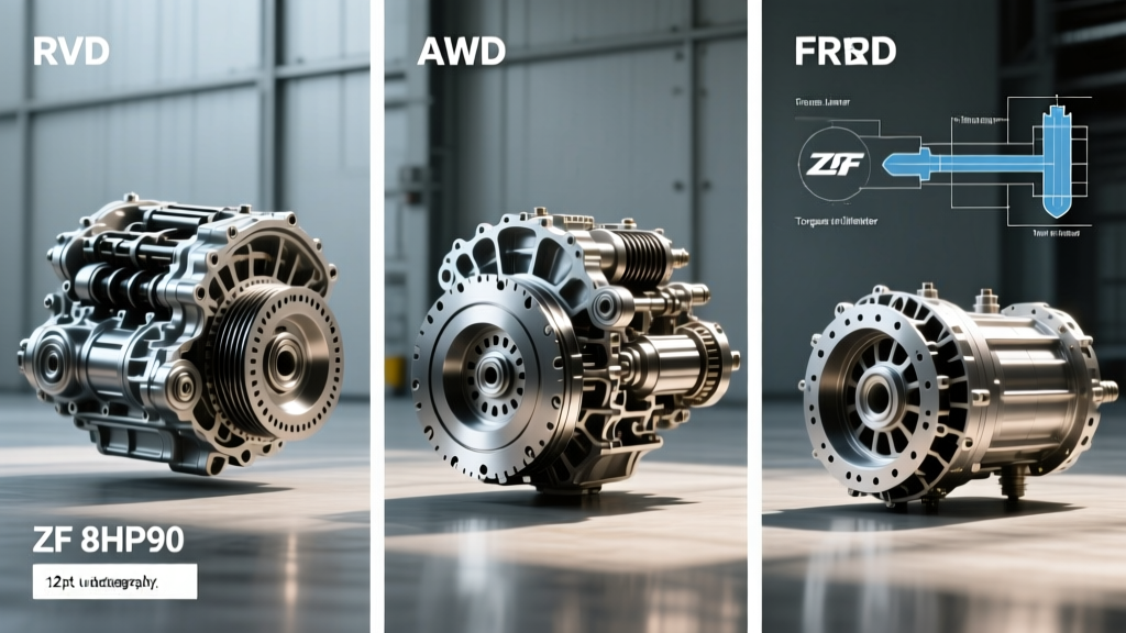
Constant Velocity (CV) axles translate power from the differential to the wheels while accommodating suspension travel. In modern European vehicles equipped with the ZF 8HP45 or 8HP70 8-speed automatic transmission, the output flange and CV axle interface is a known diagnostic hotspot.
A common symptom of ZF 8HP drivetrain malfunction is a fluid leak originating not from the pan, but from the output flange sealing sleeve. The ZF Mechatronic Sealing Sleeve (Part # 24117605304) is a plastic/steel hybrid component that degrades over time. While often associated with the bell-housing area, similar plastic sealing flanges at the output shafts can warp, leaking gear oil directly onto the CV axle inner joint.
Diagnostic Tip: If you find gear oil slung across the inner CV boot, do not immediately condemn the CV axle boot. Clean the ZF 8HP output housing and inspect the aluminum flange seal surface for pitting. A $15 seal won't fix a $400 pitted aluminum output flange.
When replacing CV axles, always use new stretch-torque axle nuts. For example, many BMW and Audi applications require a 36mm axle nut torqued to 155 lb-ft plus an additional 90-degree turn. Reusing an old stretch nut will result in wheel bearing destruction within 5,000 miles.
Differential Backlash and Gear Identification
In a VEX IQ kit, gear backlash is minimized by simply snapping parts into a rigid plastic frame. In a Ford 8.8-inch rear differential, backlash must be meticulously set using shims and a dial indicator to prevent whining and gear tooth spalling.
- Target Backlash: Typically 0.006 to 0.010 inches for street-driven 8.8 and GM 10-bolt differentials.
- Ring Gear Bolts: Must be torqued to 85 lb-ft with a medium-strength threadlocker (e.g., Loctite 243). Left-hand threads are common on certain Chrysler axles; misidentifying the thread direction will snap the bolt and ruin the ring gear.
- Friction Modifier: Clutch-type limited-slip differentials (LSD) require specific additives, such as Motorcraft XL-3. Failing to identify an LSD and omitting the modifier results in severe 'chatter' during low-speed turns, a symptom frequently misdiagnosed as a bad wheel bearing or CV joint.
The NVH (Noise, Vibration, Harshness) Troubleshooting Matrix
In 2026, professional shops utilize wireless NVH accelerometers and chassis ears to isolate drivetrain frequencies. When diagnosing symptoms without $5,000 worth of software, technicians rely on the 'Frequency vs. Speed' matrix to identify the failing component based on the physics of rotational mass.
- Tire/Wheel Frequency (1st Order): Vibration peaks between 50-70 mph and changes with vehicle speed, but not engine RPM. Caused by out-of-balance wheels or out-of-round tires. Not a drivetrain issue.
- Driveshaft Frequency (2nd/3rd Order): A high-frequency 'hum' or 'buzz' that correlates directly with driveshaft RPM (which spins 3 to 4 times faster than the wheels). Caused by driveshaft imbalance, missing weld weights, or a failing center carrier bearing. Isolate by coasting through the speed range in neutral; if the vibration remains, the driveshaft is the culprit.
- Engine/Converter Frequency: Vibration that changes strictly with engine RPM, regardless of vehicle speed. Points to a failing torque converter, cracked flexplate, or harmonic balancer separation. Common in high-mileage GM 6L80 applications where the torque converter clutch (TCC) lining delaminates.
- Coast vs. Drive Load: A howling differential pinion bearing will whine on 'coast' (deceleration), while a worn ring gear or side bearing will typically howl under 'drive' (acceleration) load.
Essential Diagnostic Tooling for the Modern Drivetrain
You cannot properly diagnose or reassemble automotive drivetrain components using the rudimentary tools found in a VEX IQ kit. Precision is non-negotiable.
- Inch-Pound Torque Wrench: Critical for setting differential preload and pinion bearing crush sleeves. A standard 1/2-inch drive clicker wrench cannot measure the 15-25 inch-pounds of rotational drag required for a proper pinion bearing setup.
- Magnetic Dial Indicator (0.001" resolution): Mandatory for measuring gear backlash and driveshaft runout. Guessing backlash by 'feel' leads to catastrophic ring and pinion failure under thermal expansion.
- Thermal Imaging Camera: A modern 2026 diagnostic staple. After a 20-mile test drive, scanning the U-joints, carrier bearings, and differential pinion snout will instantly reveal components suffering from internal friction and lubrication starvation long before they seize or fail catastrophically.
Mastering drivetrain component identification requires respecting the engineering that scales up from basic robotics to 1,000-horsepower automotive platforms. By adhering to strict torque specifications, utilizing precise measurement tools, and understanding the NVH signatures of failing parts, technicians can accurately diagnose and repair the complex drivetrains that power the modern world.
For further technical specifications on heavy-duty U-joints and yokes, consult the Spicer Parts technical library, and for transmission-specific mechatronic and output flange data, refer to the ZF Aftermarket portal.