The Architecture of Allison Electronic Control Systems
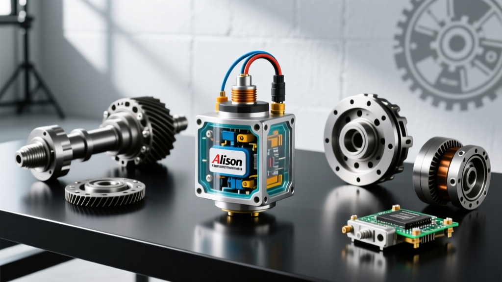
In the realm of heavy-duty and high-performance diesel applications, the electronic control systems governing the Allison 1000 and 2000 series transmissions are the undisputed nerve center of drivetrain operation. At the heart of this system is the allison transmission turbine speed sensor (TSS), a critical Hall-effect device that monitors the rotational speed of the torque converter turbine shaft. For performance builders, towing specialists, and diesel tuners operating in the 2026 landscape of high-horsepower towing, understanding and upgrading the electronic pathways surrounding the TSS is no longer optional—it is a prerequisite for reliability and aggressive shift scheduling.
The Transmission Control Module (TCM) relies on a high-resolution digital square wave signal from the TSS to calculate real-time gear ratios, monitor torque converter clutch (TCC) slip, and dictate pulse-width modulation (PWM) to the shift solenoids. When you push an Allison transmission beyond its factory torque limits, the stock electronic control infrastructure can become a bottleneck. Signal degradation, thermal sensor failure, and inadequate TCM sampling rates can lead to micro-slippage, overheating, and ultimately, catastrophic clutch pack failure.
OEM vs. Performance TSS: Part Numbers and Specifications
Before modifying the electronic control system, it is vital to understand the baseline hardware. In many Allison 1000 series applications (particularly the 5-speed and early 6-speed variants), the input (turbine) and output speed sensors share the same physical footprint and part number. However, the TCM interprets their data streams differently based on pinout mapping and software logic.
| Specification | OEM Sensor (29505632) | High-Temp Performance Variant |
|---|---|---|
| Sensor Type | Hall-Effect IC | Advanced Hall-Effect with Thermal Comp. |
| Operating Voltage | 4.75V - 5.25V Reference | 4.5V - 5.5V Tolerant |
| Max Operating Temp | 150°C (302°F) | 175°C (347°F) |
| Signal Output | 0-5V Square Wave | 0-5V Square Wave (Faster Rise Time) |
| Air Gap Tolerance | 0.5mm - 1.5mm (Fixed) | 0.5mm - 1.8mm (Extended Range) |
| Typical Cost (2026) | $85 - $120 | $160 - $220 |
Upgrading to a high-temperature variant is highly recommended for vehicles equipped with aftermarket high-stall torque converters or those subjected to sustained heavy-grade towing, where transmission fluid temperatures routinely exceed 230°F.
Thermal Degradation of Hall-Effect ICs
The primary failure mode of the stock allison transmission turbine speed sensor is not mechanical wear, but thermal degradation of the internal semiconductor. As transmission fluid temperatures spike, the internal resistance of the Hall-effect chip drifts. This causes the TCM to misread the voltage drop, resulting in phantom RPM fluctuations. The TCM's fail-safe logic will interpret this as a P0717 (Turbine Speed Sensor Circuit No Signal) or P0716 (Range/Performance) code, instantly triggering 'Limp Mode' and commanding maximum line pressure to protect the clutches.
Upgrading the Wiring Harness for Signal Integrity
The most common point of failure in the Allison electronic control system is not the sensor itself, but the wiring harness routing through the bellhousing and down to the TCM. The factory wiring utilizes standard cross-linked polyethylene (XLPE) insulation, which becomes brittle over time when exposed to the extreme radiant heat of a diesel engine block and transmission casing.
Constructing a Shielded Twisted Pair (STP) Harness
To ensure flawless signal transmission from the TSS to the TCM, performance tuners should fabricate a custom harness upgrade. This is a critical step for any electronic control system overhaul.
- Wire Selection: Use 18 AWG PTFE (Tefzel) insulated wire. PTFE offers superior dielectric strength and can withstand continuous temperatures up to 200°C.
- Shielding: The TSS signal wire and the 5V reference wire must be twisted together at a rate of 6 to 8 twists per inch. This creates a balanced line that rejects electromagnetic interference (EMI) from the alternator and high-current fuel injection wiring.
- Grounding: The sensor ground must be routed directly back to the TCM's dedicated analog ground pin, never to the engine block or chassis, to prevent ground loop voltage offsets.
- Connectors: Replace the factory plastic connector with a motorsport-grade sealed connector (such as a Deutsch DT or Autosport series) utilizing gold-plated beryllium copper pins to prevent micro-fretting corrosion.
TCM Calibration: Leveraging TSS Data for Aggressive Shift Scheduling
With the physical hardware and wiring upgraded, the next phase of optimizing the electronic control system involves TCM calibration. Modern tuning suites, such as those provided by HP Tuners and EFILive, allow tuners to manipulate how the TCM processes the data from the allison transmission turbine speed sensor.
Torque Converter Clutch (TCC) Slip Management
The TCM calculates TCC slip by subtracting the Output Speed Sensor (OSS) reading from the Turbine Speed Sensor (TSS) reading, adjusted for the current gear ratio. In a factory tune, the TCM allows for 20-40 RPM of slip during light throttle cruising to reduce driveline harshness. For high-torque applications, this slip generates excessive heat in the TCC friction material.
By modifying the TCC Apply Rate and Desired Slip tables in the TCM, tuners can command a target slip of 0-2 RPM the moment the converter reaches lockup temperature. However, this requires a flawless TSS signal; any latency in the sensor data will cause the TCM to aggressively pulse the TCC apply solenoid, leading to a violent 'chatter' that can shatter the converter hub.
Shift Adapt and Torque Phase Timing
During a gear shift, the TCM uses the TSS to monitor the 'torque phase'—the exact millisecond the off-going clutch releases and the on-coming clutch applies. By upgrading the TCM's data logging rate to 100Hz+ (a standard feature in 2026 tuning interfaces), tuners can overlay the TSS RPM drop against the commanded shift solenoid PWM. This allows for the precise adjustment of shift timing tables, ensuring that high-horsepower trucks experience seamless, flare-free shifts even when towing 20,000+ pound loads up a 6% grade.
Installation Protocols and Torque Specifications
Proper installation of the turbine speed sensor is paramount to maintaining the correct air gap between the sensor tip and the tone ring (reluctor wheel) on the turbine shaft. The Allison 1000 series utilizes a fixed-depth sensor bore, meaning the air gap is non-adjustable and relies entirely on the sensor flange seating perfectly against the transmission case.
Step-by-Step Installation Best Practices
- Bore Preparation: Clean the sensor bore in the transmission case with brake cleaner and a lint-free cloth. Any metallic debris or sludge left in the bore will prevent the sensor from seating fully, increasing the air gap and resulting in a weak, erratic signal at low RPMs.
- O-Ring Lubrication: Always install a new OEM-spec Viton O-ring. Lubricate the O-ring generously with Allison approved TES-295 or TES-668 transmission fluid. Never use petroleum jelly or silicone grease, as these will contaminate the transmission fluid and degrade the clutch friction materials.
- Fastener Torque: The sensor is retained by an M6x1.0 flange bolt. The factory specification dictates a torque value of 11 Nm (97 lb-in). Over-torquing this bolt can crack the sensor's plastic housing or strip the aluminum threads in the transmission case, while under-torquing will allow the sensor to vibrate, causing mechanical damage to the sensor tip and the tone ring.
Diagnosing P0717 and P0716 Codes in Modified Vehicles
When a modified truck throws a P0717 (No Signal) or P0716 (Range/Performance) code, the immediate assumption is often a failed sensor. However, in the context of upgraded electronic control systems, diagnostics must follow a strict logical pathway.
First, verify the 5V reference and analog ground at the sensor harness connector using a high-impedance digital multimeter. A reading below 4.8V indicates excessive resistance in the wiring harness or a failing voltage regulator inside the TCM. Next, connect an oscilloscope to the signal wire while the vehicle is on a lift. A healthy allison transmission turbine speed sensor will produce a crisp, perfectly square 0-5V waveform. If the waveform shows rounded edges, voltage sagging, or inconsistent amplitude, the issue is almost certainly EMI interference from an unshielded wiring harness or a failing alternator diode trio, rather than the sensor itself.
By treating the allison transmission turbine speed sensor not just as a standalone part, but as the foundational input for the entire electronic control system, performance builders can unlock the true potential of the Allison platform. Through meticulous wiring upgrades, precise TCM calibration, and adherence to strict installation tolerances, your heavy-duty drivetrain will deliver reliable, uncompromising performance for years to come.