The Intersection of Heat and Hydraulics in Modern Allison Builds
When pushing a 6.6L Duramax or a modern L5P 10-speed Allison platform beyond factory towing limits, the hydraulic management system becomes the primary bottleneck. The Transmission Fluid Pressure Sensor (TFPS) is the critical feedback loop that dictates shift firmness, clutch pack apply times, and overall line pressure. As we move through the 2026 tuning season, heavy-duty truck owners and performance shops are increasingly recognizing that monitoring and upgrading this specific circuit is mandatory for surviving high-torque applications.
However, pressure does not exist in a vacuum. Fluid viscosity and thermal expansion drastically alter hydraulic readings. Therefore, a comprehensive performance upgrade requires a complete understanding of the valve body's sensor topology. When planning a custom wiring harness relocation or a full valve body overhaul, understanding the exact Allison transmission temp sensor location is just as critical as servicing the pressure switch. Heat soak can cause the fluid to thin, leading to pressure drops that the TCM (Transmission Control Module) attempts to compensate for, ultimately triggering limp mode if the sensor data is flawed or delayed.
Pinpointing the Hardware: Sensor Topology on the Allison 1000 and 10-Speed
Before unbolting the deep pan, it is essential to understand where the primary sensors reside. The architecture changed significantly between the early 5-speed/6-speed Allison 1000 series and the modern 10-speed variants found in 2020+ L5P platforms.
The Transmission Fluid Pressure Sensor (TFPS)
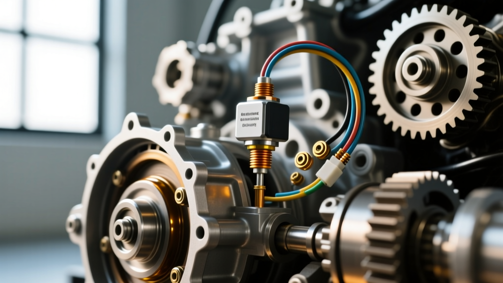
On the legendary Allison 1000 (used in LB7, LLY, LBZ, LMM, and LML Duramax engines), the TFPS is threaded directly into the cast aluminum valve body. It operates on a 5-volt reference circuit, translating hydraulic line pressure (ranging from 0 to roughly 300 psi) into a variable voltage signal sent back to the TCM. If you are upgrading to a heavy-duty billet valve body, you will transfer this sensor to the new casting.
Navigating the Thermal Circuit
While the pressure sensor is easily accessible once the pan is dropped, the Allison transmission temp sensor location varies by generation. On early models, it was often integrated into the external cooler lines or the pan itself. On the later LML and the modern 10-speed Allison (which utilizes a TEHCM - Transmission Electronic Control Hydraulic Module), the temperature sensor is integrated directly into the internal wiring harness and TEHCM assembly. This means you cannot simply swap a threaded temperature sensor; upgrading the thermal reading capability requires installing a high-response TEHCM harness or piggybacking an external data-logging sensor via an aftermarket ECU for precise tuning feedback.
Why the OEM TFPS Fails Under High-Performance Load
The OEM Allison TFPS (commonly replaced by ACDelco part number 213-4726 or GM 29548968) is designed for factory line pressures, which typically peak around 160-180 psi during wide-open throttle (WOT) shifts. When performance tuners increase desired line pressure to 220+ psi to prevent clutch slip under heavy towing or sled pulling, the OEM sensor's internal diaphragm is subjected to extreme mechanical stress and elevated fluid temperatures (often exceeding 230°F in the sump).
This leads to two primary failure modes:
- Diaphragm Fatigue: The sensor begins to read lower than actual pressure, causing the TCM to overcompensate by driving the Pressure Control (PC) solenoid to its maximum duty cycle, resulting in harsh, tire-chirping shifts and blown clutch pistons.
- Electrical Burnout: The extreme heat near the valve body degrades the sensor's internal resistance board, triggering DTC P0875 (Transmission Fluid Pressure Sensor/Switch 'D' Circuit) or P0843, instantly locking the transmission in 3rd or 4th gear limp mode.
"In 2026, we no longer recommend reusing the OEM pressure sensor on any Duramax making over 600 lb-ft of torque. The cost of a dropped pan and a ruined clutch pack far outweighs the price of a new, calibrated heavy-duty sensor and an upgraded wiring pigtail." - Lead Drivetrain Engineer, AutoGear Nexus Performance Division
OEM vs. Performance Upgrades: Data Comparison
When sourcing components for your build, it is vital to match the sensor's pressure ceiling with your TCM tuning limits. Below is a comparison of standard setups versus performance-oriented configurations.
| Parameter | OEM ACDelco (213-4726) | Heavy-Duty Aftermarket / Billet Kit | TCM Tuning Limit (HP Tuners) |
|---|---|---|---|
| Max Rated Pressure | ~290 PSI | 400+ PSI (Reinforced Diaphragm) | 240 PSI (Safe limit for OEM clutches) |
| Operating Temp Limit | 250°F (121°C) | 300°F+ (High-temp epoxy sealing) | 225°F (Sump temp alert threshold) |
| Average Cost (2026) | $65 - $85 USD | $140 - $220 USD | N/A (Software licensing applies) |
| Wiring Harness | Prone to brittle insulation | Teflon-coated, heat-shielded pigtail | Required for consistent 5V reference |
Step-by-Step Installation and Torque Specifications
Upgrading the TFPS requires strict adherence to cleanliness and torque specifications. The Allison 1000 and 10-speed platforms are highly sensitive to debris in the valve body hydraulic circuits. For a complete fluid and sensor service, expect to use approximately 12.7 quarts of Allison Approved TranSynd 668 synthetic fluid (for deep pan applications).
Execution Protocol
- Preparation: Elevate the vehicle and allow the fluid to cool to below 120°F to prevent burns, but remain warm enough to flow freely.
- Pan Removal: Remove the 18 perimeter bolts (typically 10mm or 8mm depending on the pan generation). Carefully lower the aluminum deep pan, ensuring the internal filter O-ring does not drop into the sump.
- Sensor Extraction: Locate the TFPS on the valve body. Disconnect the electrical connector by pressing the release tab. Using a deep-well socket or appropriate crowfoot wrench, unthread the sensor. Note: Inspect the threads for aluminum galling.
- Wiring Upgrade: This is the optimal time to inspect the wiring. If the loom is brittle, cut the connector back and solder in a high-temp, Teflon-insulated pigtail. Heat shrink all connections.
- Installation & Torque: Apply a single drop of blue Loctite 243 to the sensor threads. Thread the new TFPS into the valve body by hand to avoid cross-threading. Torque specification is exactly 11 Nm (97 lb-in). Do not exceed this, as the aluminum valve body threads will strip easily.
- Refill and Verify: Reinstall the pan with a new gasket (torque perimeter bolts to 24 Nm / 18 lb-ft in a crisscross pattern). Refill with TranSynd 668. Use a bidirectional scan tool to monitor the TFPS voltage at Key-On-Engine-Off (KOEO). It should read approximately 0.4V to 0.5V (representing 0 psi).
TCM Calibration: Tuning the Pressure Control Solenoid
Hardware upgrades are only half the battle. The TCM relies on the TFPS to create a closed-loop hydraulic control system. If you install a heavy-duty sensor and a performance shift kit (such as those available through Sonnax or TransGo), you must recalibrate the TCM using software like HP Tuners or EFILive.
When modifying the Desired Line Pressure tables, you are essentially telling the Pressure Control (PC) solenoid how much amperage to apply. Lower amperage equals higher line pressure. For a 2024+ L5P 10-speed Allison towing a 20,000 lb 5th-wheel, a common performance tune will bump the WOT line pressure from the factory 175 psi up to 215 psi. This ensures the clutch packs apply with enough force to prevent micro-slipping, which is the primary cause of glazing and premature failure.
However, you must also adjust the Shift Solenoid Apply/Release Timing tables. Higher line pressure results in faster, harsher shifts. If you do not slightly increase the shift time (in milliseconds) to cushion the apply phase, the driveline shock can shatter transfer case chains or U-joints. For comprehensive tuning parameters and supported vehicle databases, referencing the HP Tuners Supported Vehicles portal is highly recommended before purchasing VCM credits.
Diagnostic Edge Cases: When the Sensor is Not the Problem
Before replacing the TFPS, verify that the issue is not stemming from the Pressure Control (PC) Solenoid itself or a stuck pressure regulator valve in the valve body. As documented in various Allison Transmission support bulletins, a worn pressure regulator bore will cause hydraulic leaks that the TFPS accurately detects and reports to the TCM. In these cases, the sensor is doing its job perfectly by triggering a low-pressure code (P0868), but the root cause is mechanical valve body wear, not electrical sensor failure. Always monitor live data comparing Desired Pressure vs. Actual Pressure while driving under load before condemning the sensor.