The Thermal Crisis in Modern Drivetrains
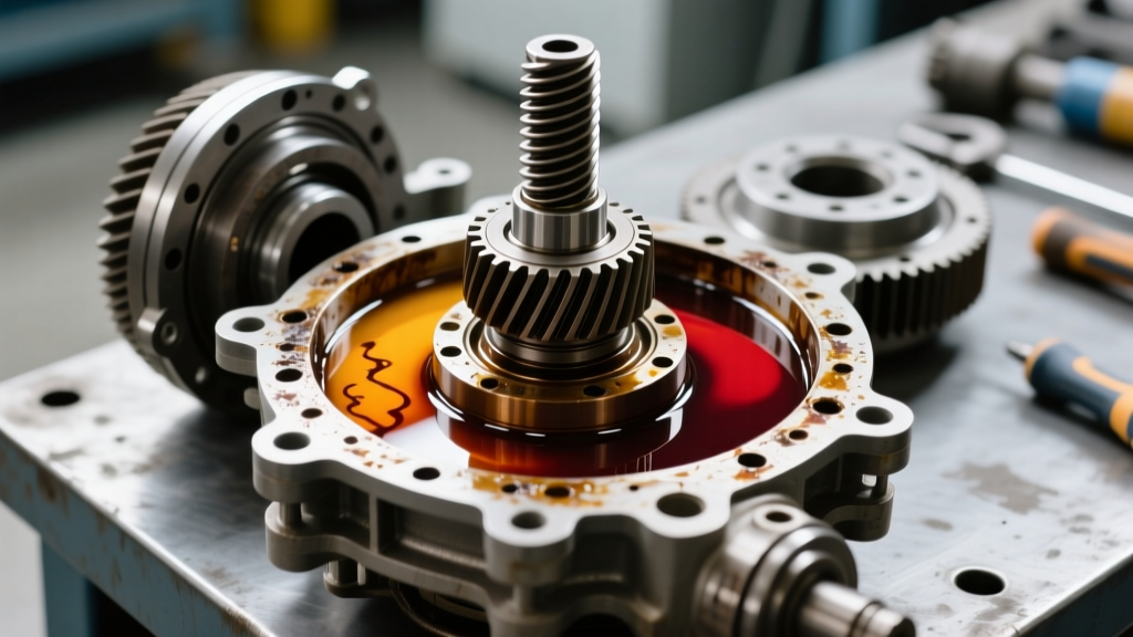
As we navigate the 2026 landscape of heavy-duty towing, overlanding, and high-torque electric vehicle (EV) drivetrains, the thermal limits of traditional hypoid gearsets are being tested like never before. In axles such as the Dana 80, AAM 11.5, and Ford 10.5-inch 35-spline, the sliding friction inherent to hypoid ring and pinion gears generates immense localized heat. When differential fluid temperatures exceed 250°F (121°C), the shear stability of conventional gear oils breaks down, leading to additive precipitation, base oil oxidation, and catastrophic bearing failure.
While passive finned differential covers offer marginal improvements in convective heat transfer, they are entirely insufficient for sustained high-load scenarios. This reality has driven a massive shift toward active differential cooling systems—pump-driven fluid loops that route hot gear oil through external stacked-plate coolers. However, designing and validating these systems requires precise fluid dynamics engineering, specifically the use of a differential pressure flow meter to measure the flow of highly viscous, particulate-laden gear oil without restricting the circuit.
Anatomy of an Active Differential Cooling Loop
An active cooling loop fundamentally alters the thermodynamics of the axle housing. Instead of relying on the splashing action of the ring gear to distribute oil, a dedicated positive-displacement pump extracts fluid directly from the sump, pushes it through an external heat exchanger, and injects it back into the differential cover via targeted spray galleries.
Differential Cover Selection and Porting
The foundation of any active loop is a high-capacity, ported differential cover. Aftermarket leaders like Mag-Hytec and PML engineer sand-cast aluminum covers featuring internal baffles and pre-tapped NPT ports. For a heavy-duty application, a cover with a minimum of two 1/4-inch or 3/8-inch NPT ports is mandatory: one for the pump suction (drawn from the lowest point of the sump) and one for the cooler return (routed to an internal spray tube aimed directly at the pinion bearing and ring gear mesh point).
Engineering Insight: Never use the factory fill or drain plugs for active loop plumbing. The suction line must draw from a custom low-point port to prevent cavitation, while the return line must utilize an internal distribution tube to ensure the critical pinion bearing receives a constant stream of cooled, pressurized oil.
Validating Flow with a Differential Pressure Flow Meter
When engineering or tuning an active differential cooling system, measuring the exact flow rate of 75W-90 or 75W-140 synthetic gear oil is notoriously difficult. Standard mechanical turbine flow meters or paddlewheel sensors fail rapidly in this environment. The high kinematic viscosity of gear oil (often exceeding 24 cSt at 100°C) causes severe stiction on moving parts, and the inevitable metallic wear particulates suspended in the fluid will destroy a turbine's bearings within hours.
To solve this, drivetrain engineers and advanced tuning shops utilize a differential pressure flow meter. This device operates on Bernoulli’s principle, measuring the pressure drop ($\Delta P$) across a precisely machined restriction (such as an orifice plate or Venturi tube) installed in the cooling line. Because there are no moving parts in the flow stream, the meter is entirely immune to the abrasive metallic debris and high viscosity of hypoid gear lubricants.
The Physics of Viscous Flow Measurement
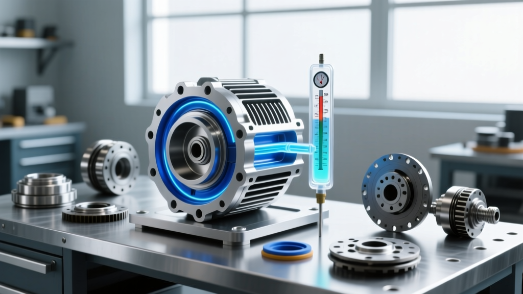
A differential pressure flow meter uses flush-mounted piezoresistive transducers to read the upstream and downstream pressures. The flow rate ($Q$) is calculated using the square root relationship of the pressure differential:
Q = K * √(ΔP / ρ)
Where K is the discharge coefficient of the orifice, ΔP is the pressure drop, and ρ is the fluid density. Because gear oil density and viscosity fluctuate with temperature, modern active differential cooling systems integrate a inline RTD (Resistance Temperature Detector) to allow the ECU to dynamically compensate the differential pressure flow meter's readings, ensuring the pump maintains a target flow rate of 1.5 to 2.5 Gallons Per Minute (GPM) regardless of whether the axle is at 40°F or 220°F.
Thermal Rejection and Flow Rate Data
Understanding the relationship between flow rate, cooler capacity, and heat rejection is critical for preventing gear oil degradation. Below is a comparative analysis of differential cooling configurations tested under sustained 85% load conditions (simulating a 12,000 lb trailer on a 6% grade).
| Cooling Configuration | Fluid Flow Rate (GPM) | Avg. Sump Temp (°F) | Heat Rejection (BTU/hr) | Estimated Cost (USD) |
|---|---|---|---|---|
| OEM Stamped Steel Cover (Passive) | 0 (Splash Only) | 265°F | N/A (Radiant Only) | $0 |
| Finned Aluminum Cover (Passive) | 0 (Splash Only) | 242°F | ~800 | $150 - $250 |
| Active Loop (Small 12V Pump) | 0.8 GPM | 215°F | 4,500 | $600 - $850 |
| Active Loop (Pos-Displacement Pump) | 2.2 GPM (Verified via DP Meter) | 185°F | 12,500 | $1,200 - $1,600 |
Data synthesized from heavy-duty drivetrain thermal bench testing. Target sump temperature for optimal 75W-140 synthetic shear stability is 180°F - 200°F.
Pump Selection and Cavitation Risks
The data above highlights a common pitfall: using standard 12V centrifugal water pumps for gear oil. Centrifugal pumps rely on low-viscosity fluids to generate head pressure. When subjected to 75W-140 gear oil, a centrifugal pump will experience massive internal slip, delivering less than 0.5 GPM while drawing excessive amperage.
For active differential cooling, you must use a positive displacement gear pump or a progressive cavity pump. These pumps physically trap a fixed volume of the thick oil and force it through the lines. When paired with a differential pressure flow meter, engineers can monitor the $\Delta P$ across the external cooler. If the pressure differential spikes unexpectedly, it indicates either a severe drop in ambient temperature (increasing oil viscosity) or a blockage in the stacked-plate cooler, allowing the system's controller to trigger a bypass valve to prevent hose rupture.
Precision Assembly: Torque Specs and Sealing
Installing a ported differential cover and integrating an active cooling loop requires strict adherence to torque specifications and sealing protocols. A leak in an active, pressurized system will rapidly drain the axle sump, leading to instant ring and pinion destruction.
Fastener and Sealing Data
- Dana 60 / Dana 70 (3/8"-16 Bolts): Torque to 30-35 lb-ft. Use a high-tack gasket or RTV.
- Dana 80 / AAM 11.5 (M10x1.5 Bolts): Torque to 35-40 lb-ft. Clean mating surfaces with brake cleaner.
- Ford 10.5-inch (3/8" Bolts): Torque to 32 lb-ft. Ensure the internal suction tube does not interfere with the ring gear rotation (maintain minimum 0.250" clearance).
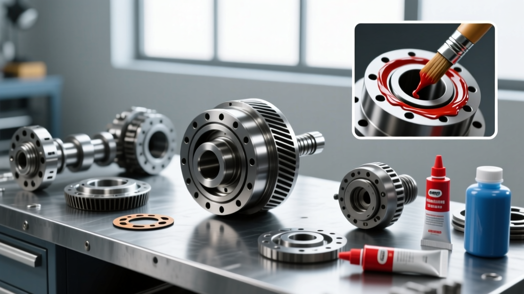
- Sealant Selection: If using RTV instead of a reusable elastomer gasket (like a LubeLocker), use Permatex Ultra Black (Part #598BR). It is specifically formulated for high-flex, high-oil-contamination environments. Allow a full 24-hour cure time before filling with fluid and pressurizing the active loop.
Fluid Selection for Pressurized Loops
When running an active system validated by a differential pressure flow meter, fluid selection is paramount. Avoid conventional mineral-based 80W-90 oils, as their viscosity index (VI) is too low, meaning they will thin out excessively at the cooler return and cause pressure drops. Opt for a full synthetic 75W-140 with a high treat-rate of VI improvers and extreme pressure (EP) additives, such as AMSOIL Severe Gear or Mobil 1 Synthetic Gear Lubricant. These fluids maintain a stable kinematic viscosity across the wide thermal deltas introduced by external stacked-plate coolers, ensuring the differential pressure flow meter reads accurately and the hypoid gearset remains protected under the most extreme 2026 towing and performance demands.